Subaru Crosstrek Service Manual: Installation
DRIVE SHAFT SYSTEM > Front Hub Unit Bearing
INSTALLATION
1. Place the front brake back plate between the front axle housing and the front hub unit bearing, and tighten the bolt.
CAUTION:
• Do not get closer the tool which charged magnetism to magnetic encoder.
• Be careful not to damage the magnetic encoder.
• Use a new bolt.
Tightening torque:
65 N·m (6.6 kgf-m, 47.9 ft-lb)
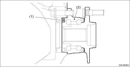
(1) | Magnetic encoder | (2) | Front hub unit bearing |
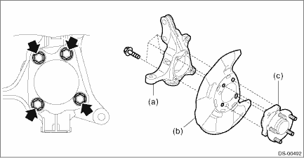
(a) | Front axle housing | (b) | Front brake back plate | (c) | Front hub unit bearing |
Tightening torque:
65 N·m (6.6 kgf-m, 47.9 ft-lb)
2. Install the front drive shaft assembly.
CAUTION:
• Do not hammer the drive shaft assembly when installing.
• Use new axle nuts.
(1) Insert the drive shaft assembly into the hub spline, and pull it into the specified position.
(2) Tighten the axle nut temporarily.
3. Install the disc rotor to the front hub unit bearing.
4. Install the caliper body assembly to the front axle housing.
Tightening torque:
Refer to “COMPONENT” of “General Description” for the tightening torque. General Description > COMPONENT">
5. Install the brake hose bracket.
Tightening torque:
33 N·m (3.4 kgf-m, 24.3 ft-lb)
6. Install the front ABS wheel speed sensor.
Tightening torque:
7.5 N·m (0.8 kgf-m, 5.5 ft-lb)
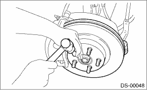
7. While pressing the brake pedal, tighten the new axle nuts to the specified torque.
CAUTION:
Do not load the front axle before tightening the axle nut. Doing so may damage the hub unit bearing.
Tightening torque:
220 N·m (22.4 kgf-m, 162.3 ft-lb)
8. After tightening the axle nut, lock it securely.
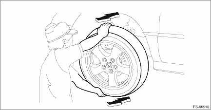
9. Install the front wheels, and perform the following inspections.
Tightening torque:
Except for C4 model: 120 N·m (12.2 kgf-m, 88.5 ft-lb)
C4 model: 100 N·m (10.2 kgf-m, 73.8 ft-lb)
(1) Check the wheels for smooth rotation.
(2) Check that there is no looseness by moving the upper and lower portions of front tire in an axial direction with the brake pedal released.
• Looseness exists > Check the front hub unit bearing. Front Hub Unit Bearing > INSPECTION">
(3) Check that there is no looseness by moving the upper and lower portions of front tire in an axial direction with the brake pedal depressed.
• Looseness exists > Replace the ball joint assembly. Front Ball Joint > REMOVAL">
 Inspection
DRIVE SHAFT SYSTEM > Front Hub Unit BearingINSPECTION1. Moving the front tire up and down by hand, check there is no looseness in bearing, and check the wheel rotates smoothly.CAUTION:If there is u ...

Other materials:
Dtc b1401 meter collation
IMMOBILIZER (DIAGNOSTICS) > Diagnostic Procedure with Diagnostic Trouble Code (DTC)DTC B1401 METER COLLATIONDTC DETECTING CONDITION:Reference code incompatibility between combination meter and body integrated unitCAUTION:When the combination meter is replaced, registration of the immobilizer syst ...
Dtc b2327 rear radar internal failure (internal electric circuit)
Blind Spot Detection/Rear Cross Traffic Alert (DIAGNOSTICS) > Diagnostic Procedure with Diagnostic Trouble Code (DTC)DTC B2327 REAR RADAR INTERNAL FAILURE (INTERNAL ELECTRIC CIRCUIT)DTC DETECTING CONDITION:Defective radar sensorTROUBLE SYMPTOM:• All functions of BSD/RCTA stop.• Fail i ...
Checking the coolant level
WARNING
Never attempt to remove the radiator
cap until the engine has been
shut off and has cooled down
completely. Since the coolant is
under pressure, you may suffer
serious burns from a spray of boiling
hot coolant when the cap is
removed.
"FULL" level mark
"LOW" level mark
C ...
