Subaru Crosstrek Service Manual: Installation
DRIVE SHAFT SYSTEM > Front Drive Shaft
INSTALLATION
1. Before installation, check the drive shaft assembly. Front Drive Shaft > INSPECTION">
2. Replace the differential side retainer oil seal with a new part.
• MT model: Differential Side Retainer Oil Seal > REPLACEMENT">
• CVT model: Differential Side Retainer Oil Seal > REPLACEMENT">
NOTE:
After pulling out the drive shaft assembly, be sure to replace with a new oil seal.
3. Insert the drive shaft assembly into the hub spline, and pull it into the specified position.
CAUTION:
Do not hammer the drive shaft assembly when installing.
4. Tighten the axle nut temporarily.
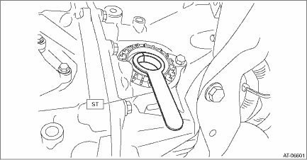
5. Using the ST, install the front drive shaft assembly to the transmission.
Preparation tool:
ST: OIL SEAL PROTECTOR (28399SA010)
6. Install the ball joint assembly to the front axle housing.
CAUTION:
Before tightening, make sure the lower side of front axle housing and stepped section of ball joint are in contact.
Tightening torque:
50 N·m (5.1 kgf-m, 36.9 ft-lb)
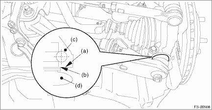
(a) | Lower side of front axle housing | (c) | Front axle housing | (d) | Ball joint |
(b) | Raised section of ball joint |
7. Install the stabilizer link.
Tightening torque:
60 N·m (6.1 kgf-m, 44.3 ft-lb)
8. While pressing the brake pedal, tighten the new axle nuts to the specified torque.
CAUTION:
Do not load the front axle before tightening the axle nut. Doing so may damage the hub unit bearing.
Tightening torque:
220 N·m (22.4 kgf-m, 162.3 ft-lb)
9. After tightening axle nut, lock it securely.
10. Fill transmission gear oil. (MT model)
11. Fill differential gear oil. (CVT model)
12. Install the front wheels.
Tightening torque:
Except for C4 model: 120 N·m (12.2 kgf-m, 88.5 ft-lb)
C4 model: 100 N·m (10.2 kgf-m, 73.8 ft-lb)
13. Inspect the wheel alignment and adjust if necessary.
• Inspection: Wheel Alignment > INSPECTION">
• Adjustment: Wheel Alignment > ADJUSTMENT">
CAUTION:
When the wheel alignment has been adjusted, perform “VDC sensor midpoint setting mode”. VDC Control Module and Hydraulic Control Unit (VDCCM&H/U) > ADJUSTMENT"> VDC Control Module and Hydraulic Control Unit (VDCCM&H/U) > ADJUSTMENT"> VDC Control Module and Hydraulic Control Unit (VDCCM&H/U) > ADJUSTMENT">
14. Perform reinitialization of the auto headlight beam leveler system. (Model with auto headlight beam leveler) Auto Headlight Beam Leveler System > PROCEDURE">
 Inspection
DRIVE SHAFT SYSTEM > Front Drive ShaftINSPECTIONCheck the removed parts for damage, wear, corrosion etc. If faulty, repair or replace.• PTJ (pillow tripod joint)Check for seizure, corrosion, ...

Other materials:
Installation
MECHANICAL(H4DO) > Timing Chain AssemblyINSTALLATION1. TIMING CHAIN LHNOTE:• Be careful that the foreign matter is not into or onto the assembled component during installation.• Apply engine oil to all component parts of the timing chain.1. Prepare to attach the chain tensioner LH.(1) ...
Dtc u0402 invalid data received from tcm
LAN SYSTEM (DIAGNOSTICS) > Diagnostic Procedure with Diagnostic Trouble Code (DTC)DTC U0402 INVALID DATA RECEIVED FROM TCMDTC detecting condition:Received error data from TCM.Trouble symptom:Sport indicator light blinks.STEPCHECKYESNO1.CHECK PERFORMING OF BASIC DIAGNOSTIC PROCEDURE.Was the basic ...
Enabling functions
When the procedure to disable the functions
is performed again, a chirp sound will
be heard, and the functions are enabled.
NOTE
The keyless access function will be
enabled only if you perform the procedure
in the same manner you disabled
the function (for example, when disabling
by o ...
