Subaru Crosstrek Service Manual: Installation
COOLING(H4DO) > Water Pipe Assembly
INSTALLATION
1. WATER PIPE ASSEMBLY RH
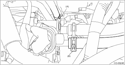
1. Set the water pipe assembly RH on the engine, and connect the water pipe hose RH (B) to the oil pan upper.
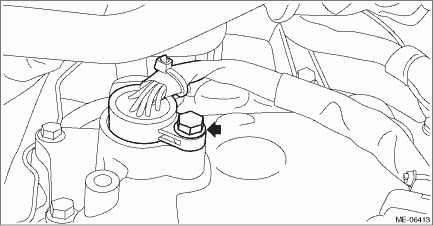
2. Secure the water pipe assembly RH to the cylinder head RH with bolt (A).
Tightening torque:
6.4 N·m (0.7 kgf-m, 4.7 ft-lb)
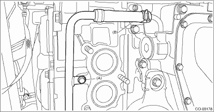
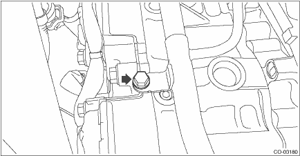
3. Install the bolt (B) which secures the water pipe assembly RH to the cam carrier RH.
Tightening torque:
6.4 N·m (0.7 kgf-m, 4.7 ft-lb)
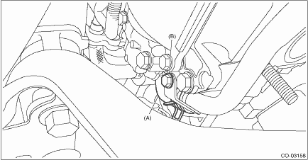
4. Connect the water hose (A) to the water pipe assembly RH.
5. Install the front exhaust pipe. Front Exhaust Pipe > INSTALLATION">
6. Connect the battery ground terminal. NOTE">
7. Fill engine coolant. Engine Coolant > REPLACEMENT">
2. WATER PIPE ASSEMBLY LH
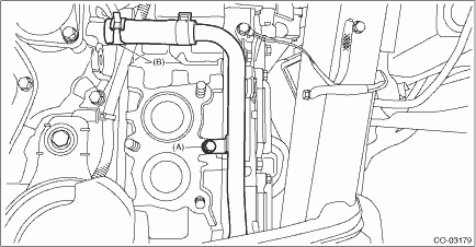
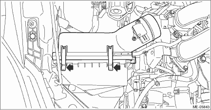
1. Set the water pipe assembly LH on the engine, and connect the water pipe hose LH (B) to the oil pan upper.
2. Secure the water pipe assembly LH to the cylinder head LH with bolt (A).
Tightening torque:
6.4 N·m (0.7 kgf-m, 4.7 ft-lb)
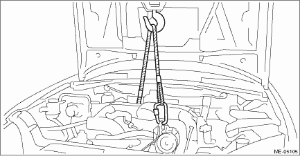
3. Lower the engine and remove the lifting device and wire ropes.
4. Remove the bolt and turn the transmission harness counterclockwise to install the transmission harness to the control valve body. (CVT model)
Tightening torque:
7 N·m (0.7 kgf-m, 5.2 ft-lb)
5. Install the bolt which holds the transmission harness stay. (CVT model)
Tightening torque:
7 N·m (0.7 kgf-m, 5.2 ft-lb)
6. Install the transmission case cover. (CVT model)
Tightening torque:
8 N·m (0.8 kgf-m, 5.9 ft-lb)
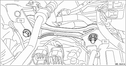
7. Install the pitching stopper.
Tightening torque:
T1: 50 N·m (5.1 kgf-m, 36.9 ft-lb)
T2: 58 N·m (5.9 kgf-m, 42.8 ft-lb)
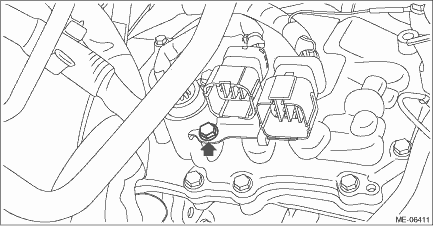
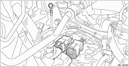
8. Connect the transmission radio ground terminal (C) to the vehicle body, and connect the bulkhead harness connector to the transmission harness connector (A) and the inhibitor harness connector (B). (CVT model)
Tightening torque:
13 N·m (1.3 kgf-m, 9.6 ft-lb)
9. Lift up the vehicle.
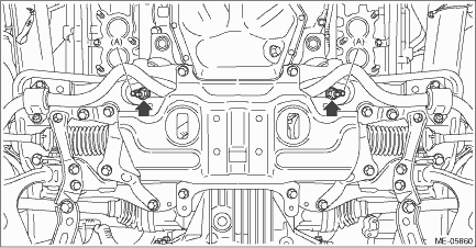
10. Install the nuts which hold the engine mounting to the front crossmember. (CVT model)
NOTE:
• Make sure that locators (A) of the engine mounting are securely inserted.
• Use a new nut.
Tightening torque:
60 N·m (6.1 kgf-m, 44.3 ft-lb)
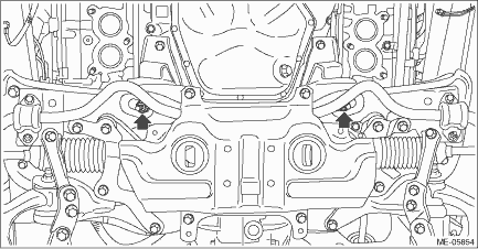
11. Install the nuts which hold the engine mounting to the front crossmember. (MT model)
NOTE:
Use a new nut.
Tightening torque:
60 N·m (6.1 kgf-m, 44.3 ft-lb)
12. Install the front exhaust pipe. Front Exhaust Pipe > REMOVAL">
13. Lower the vehicle.
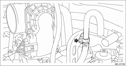
14. Secure the air breather hose to the engine rear hanger using clip. (MT model)
15. Install the bolt which secures the water pipe assembly LH to the cylinder head LH.
Tightening torque:
6.4 N·m (0.7 kgf-m, 4.7 ft-lb)
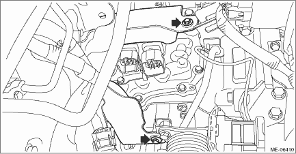
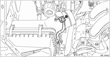
16. Connect the preheater hose (A) and the heater outlet hose (B) to the water pipe assembly LH.
17. Install the air intake case (rear).
18. Install the clip (A) which secures the air flow and intake air temperature sensor harness, and connect the connector to the air flow and intake air temperature sensor.
19. Install the air intake boot. Air Intake Boot > INSTALLATION">
20. Install the air intake duct. Air Intake Duct > INSTALLATION">
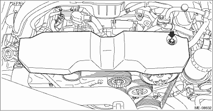
21. Install the V-belt cover.
Tightening torque:
7 N·m (0.7 kgf-m, 5.2 ft-lb)
22. Connect the battery ground terminal. NOTE">
23. Fill engine coolant. Engine Coolant > REPLACEMENT">
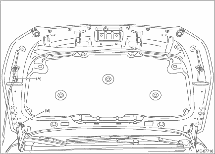
24. Change the front hood stay position from (B) to (A).
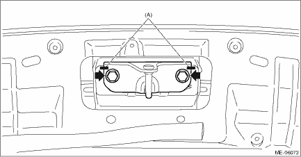
25. Install the front hood striker to the front hood by aligning the alignment marks (A), and close the front hood.
Tightening torque:
33 N·m (3.4 kgf-m, 24.3 ft-lb)
 Removal
COOLING(H4DO) > Water Pipe AssemblyREMOVAL1. WATER PIPE ASSEMBLY RH1. Disconnect the ground cable from battery. NOTE">2. Drain engine coolant. Engine Coolant > REPLACEMENT">3. ...
 Water pump
...
Other materials:
Preparation tool
FRONT SUSPENSION > General DescriptionPREPARATION TOOL1. SPECIAL TOOLILLUSTRATIONTOOL NUMBERDESCRIPTIONREMARKS927680000INSTALLER & REMOVER SETUsed for replacing the bushing front - front arm of front arm assembly.20299AG000REMOVER• Used for replacing the bushing rear - front arm of fron ...
Dtc p2007 tgv control stuck closed bank 2
ENGINE (DIAGNOSTICS)(H4DO) > Diagnostic Procedure with Diagnostic Trouble Code (DTC)DTC P2007 TGV CONTROL STUCK CLOSED BANK 2DTC DETECTING CONDITION:Immediately at fault recognitionCAUTION:After servicing or replacing faulty parts, perform Clear Memory Mode Clear Memory Mode > OPERATION" ...
Inspection
SEATS > Front SeatINSPECTION1. SEAT COVERCheck that there is no tear or fray on the cover COMPL - front backrest and the cover - front cushion.NOTE:For model with side airbag, if the door side of the cover COMPL - front backrest is torn or frayed, the side airbag may not be deployed properly. In ...
