
Subaru Crosstrek Service Manual: Installation
CONTINUOUSLY VARIABLE TRANSMISSION(TR580) > Transmission Mounting System
INSTALLATION
1. PITCHING STOPPER
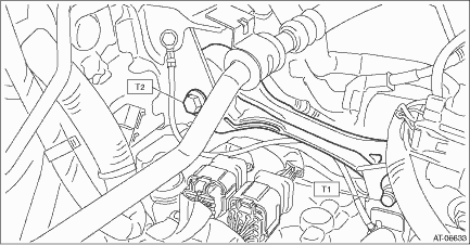
1. Install the pitching stopper.
Tightening torque:
T1: 50 N·m (5.1 kgf-m, 36.9 ft-lb)
T2: 58 N·m (5.9 kgf-m, 42.8 ft-lb)
2. Install the air intake boot assembly. Air Intake Boot > INSTALLATION">
3. Connect the battery ground terminal.
2. TRANSMISSION REAR CROSSMEMBER AND REAR CUSHION RUBBER
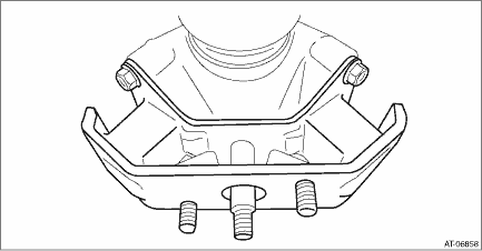
1. Attach the rear cushion rubber to the transmission.
Tightening torque:
40 N·m (4.1 kgf-m, 29.5 ft-lb)
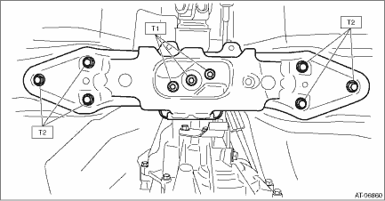
2. Install the crossmember.
Tightening torque:
T1: 35 N·m (3.6 kgf-m, 25.8 ft-lb)
T2: 70 N·m (7.1 kgf-m, 51.6 ft-lb)
3. Remove the transmission jack.
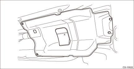
4. Install the center exhaust cover.
Tightening torque:
18 N·m (1.8 kgf-m, 13.3 ft-lb)
5. Install the center exhaust pipe. Center Exhaust Pipe > INSTALLATION">
6. Connect the battery ground terminal.
 Removal
CONTINUOUSLY VARIABLE TRANSMISSION(TR580) > Transmission Mounting SystemREMOVAL1. PITCHING STOPPER1. Disconnect the ground cable from battery. NOTE">NOTE:For model with battery sensor, dis ...

Other materials:
Replacement
MANUAL TRANSMISSION AND DIFFERENTIAL(5MT) > Differential Side Retainer Oil SealREPLACEMENT1. Disconnect the ground cable from battery.2. Remove the front tires.3. Lift up the vehicle.4. Using the TORX® bit T70, remove the drain plug, and drain the transmission gear oil completely.CAUTION:• ...
Electrical specification
POWER ASSISTED SYSTEM (POWER STEERING) (DIAGNOSTICS) > Control Module I/O SignalELECTRICAL SPECIFICATIONNOTE:The terminal numbers of the power steering control module connectors are as indicated in the figure.ContentsTerminal No.Input/output signalMeasured value and measuring conditionsPower supp ...
Dtc p000a "a" camshaft position slow response bank 1
ENGINE (DIAGNOSTICS)(H4DO) > Diagnostic Procedure with Diagnostic Trouble Code (DTC)DTC P000A "A" CAMSHAFT POSITION SLOW RESPONSE BANK 1NOTE:For the diagnostic procedure, refer to DTC P0011. Diagnostic Procedure with Diagnostic Trouble Code (DTC) > DTC P0011 "A" CAMSHAFT P ...
