Subaru Crosstrek Service Manual: Installation
CONTINUOUSLY VARIABLE TRANSMISSION(TR580) > Transmission Harness
INSTALLATION
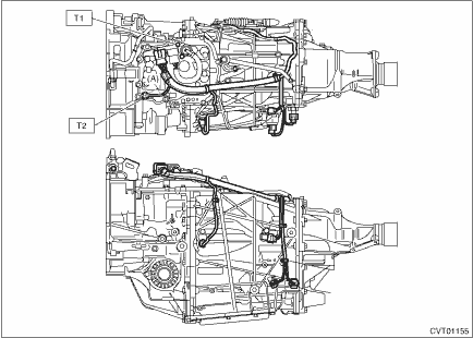
1. INHIBITOR HARNESS
Install in the reverse order of removal.
NOTE:
Install the transmission ground terminal in the direction within the range of approx. 30° (A).
Tightening torque:
T1: 7 N·m (0.7 kgf-m, 3.7 ft-lb)
T2: 14 N·m (1.4 kgf-m, 10.3 ft-lb)
2. TRANSMISSION HARNESS
1. Clean the mating surface of valve cover and transmission side.
CAUTION:
When cleaning the mating surface of the transmission side, be careful not to allow any dust, foreign matter and used liquid gasket to enter the transmission.
2. Check the control valve body for dust and other foreign matter.
3. Install the O-ring to the transmission harness.
NOTE:
• Use new O-rings.
• Apply CVTF to the O-rings.
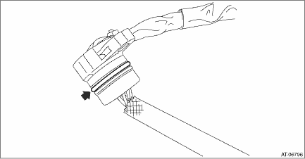
4. Install the transmission harness to the valve cover.
Tightening torque:
7 N·m (0.7 kgf-m, 5.2 ft-lb)
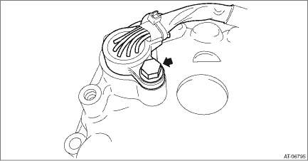
5. Install the gasket to the transmission.
NOTE:
Use a new gasket.
6. Apply liquid gasket to the oval hole of gasket.
Liquid gasket:
THREE BOND 1215B or equivalent
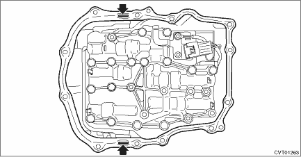
7. Connect the transmission harness connector to the control valve body, and install the valve cover.
CAUTION:
Be careful not to catch the sheet of the ST.
Tightening torque:
8 N·m (0.8 kgf-m, 5.9 ft-lb)
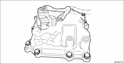
8. Remove the ST (SHEET SPECIAL TOOL).
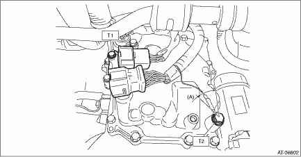
9. Install the transmission harness connector to the harness stay.
10. Install the transmission harness stay and transmission ground terminal.
NOTE:
Install the transmission ground terminal in the direction within the range of approx. 30° (A).
Tightening torque:
T1: 7 N·m (0.7 kgf-m, 5.2 ft-lb)
T2: 14 N·m (1.4 kgf-m, 10.3 ft-lb)
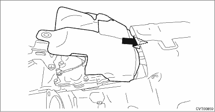
11. Insert the transmission case cover (small) between the transmission case cover (large) and the transmission to install.
Tightening torque:
8 N·m (0.8 kgf-m, 5.9 ft-lb)
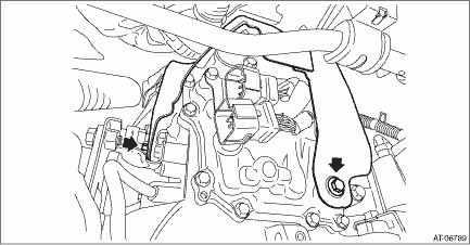
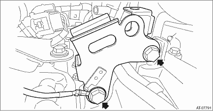
12. Install the pitching stopper bracket and transmission radio ground cord.
CAUTION:
Be careful not to deform or damage the terminal of transmission radio ground cord.
Tightening torque:
41 N·m (4.2 kgf-m, 30.2 ft-lb)
13. Install the air breather hose to the pitching stopper bracket.
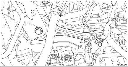
14. Install the pitching stopper.
Tightening torque:
T1: 50 N·m (5.1 kgf-m, 36.9 ft-lb)
T2: 58 N·m (5.9 kgf-m, 42.8 ft-lb)
15. Connect the following harness connectors.
• Transmission harness connectors
• Inhibitor harness connector
• Transmission radio ground terminal
Tightening torque:
13 N·m (1.3 kgf-m, 9.6 ft-lb)
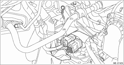
(A) | Transmission harness connectors |
(B) | Inhibitor harness connector |
(C) | Transmission radio ground terminal |
16. Install the air intake boot assembly. Air Intake Boot > INSTALLATION">
17. Adjust the CVTF level. CVTF > ADJUSTMENT">
 Removal
CONTINUOUSLY VARIABLE TRANSMISSION(TR580) > Transmission HarnessREMOVAL1. INHIBITOR HARNESS1. Remove the transmission from the vehicle. Automatic Transmission Assembly > REMOVAL">2. Rem ...
Other materials:
Brake system warning light (red)
The
light illuminates with the parking
brake applied while the ignition switch is
in the "ON" position. It turns off when the
parking brake is fully released.
WARNING
Driving with the brake system
warning light on is dangerous.
This indicates your brake system
may not be working ...
Dtc c0054 bls off malfunction
VEHICLE DYNAMICS CONTROL (VDC) (DIAGNOSTICS) > Diagnostic Procedure with Diagnostic Trouble Code (DTC)DTC C0054 BLS OFF MALFUNCTIONDTC detecting condition:Defective stop light switchTrouble symptom:• VDC does not operate.• EyeSight does not operate.Wiring diagram:Vehicle dynamics cont ...
Dtc c2533 control module board temperature sensor
POWER ASSISTED SYSTEM (POWER STEERING) (DIAGNOSTICS) > Diagnostic Procedure with Diagnostic Trouble Code (DTC)DTC C2533 CONTROL MODULE BOARD TEMPERATURE SENSORTROUBLE SYMPTOM:The steering wheel operation feels heavy.NOTE:When this code is displayed, replace the power steering control module with ...

