Subaru Crosstrek Service Manual: Installation
CONTINUOUSLY VARIABLE TRANSMISSION(TR580) > Control Valve Body
INSTALLATION
1. Clean the mating surface of valve cover and transmission side.
CAUTION:
When cleaning the mating surface of the transmission side, be careful not to allow any dust, foreign matter and used liquid gasket to enter the transmission.
2. Check the control valve body for dust and other foreign matter.
3. Install the O-rings.
NOTE:
• Use new O-rings.
• Apply CVTF to the O-rings.
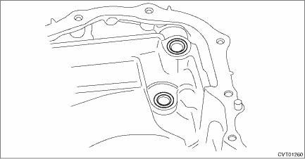
4. Install the control valve body.
(1) Install the control valve body to the transmission.
CAUTION:
• Do not damage the O-ring.
• Perform installation so that the O-ring is not displaced.
(2) Temporarily tighten the bolt (A: silver).
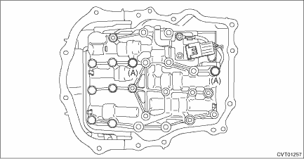
(3) Attach the bolt (B).
Tightening torque:
9 N·m (0.9 kgf-m, 6.6 ft-lb)
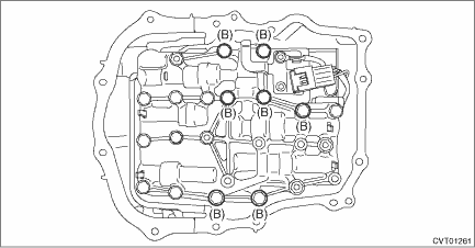
(4) Tighten the bolt (A: silver).
Tightening torque:
9 N·m (0.9 kgf-m, 6.6 ft-lb)
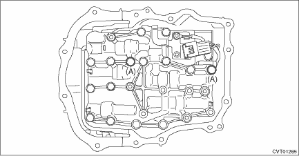
5. Install the O-ring to the transmission harness.
NOTE:
• Use new O-rings.
• Apply CVTF to the O-rings.
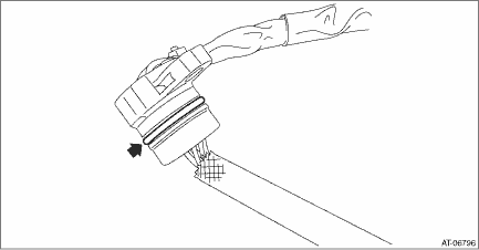
6. Install the transmission harness to the valve cover.
Tightening torque:
7 N·m (0.7 kgf-m, 5.2 ft-lb)
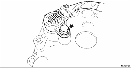
7. Install the gasket to the transmission.
NOTE:
Use a new gasket.
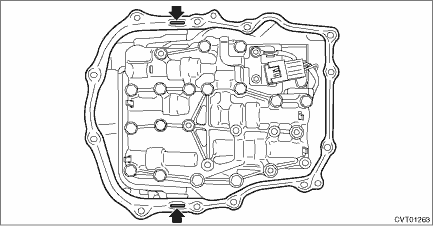
8. Apply liquid gasket to the oval hole of gasket.
Liquid gasket:
THREE BOND 1215B or equivalent
9. Connect the transmission harness connector to the control valve body, and install the valve cover.
CAUTION:
Be careful not to catch the sheet of the ST.
Tightening torque:
8 N·m (0.8 kgf-m, 5.9 ft-lb)
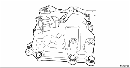
10. Remove the ST (SHEET SPECIAL TOOL).
11. Install the throttle body. Throttle Body > INSTALLATION">
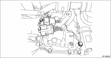
12. Install the transmission harness connector to the harness stay.
13. Install the transmission harness stay and transmission ground terminal.
NOTE:
Install the transmission ground terminal in the direction within the range of approx. 30° (A).
Tightening torque:
T1: 7 N·m (0.7 kgf-m, 5.2 ft-lb)
T2: 14 N·m (1.4 kgf-m, 10.3 ft-lb)
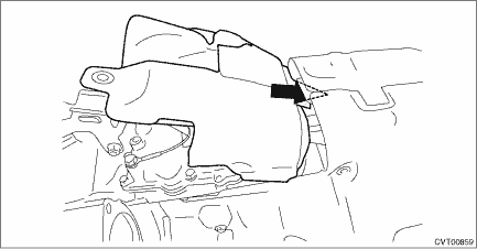
14. Insert the transmission case cover (small) between transmission case cover (large) and transmission to install.
Tightening torque:
8 N·m (0.8 kgf-m, 5.9 ft-lb)
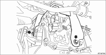
15. Install the pitching stopper bracket and transmission radio ground cord.
CAUTION:
Be careful not to deform or damage the terminal of transmission radio ground cord.
Tightening torque:
41 N·m (4.2 kgf-m, 30.2 ft-lb)
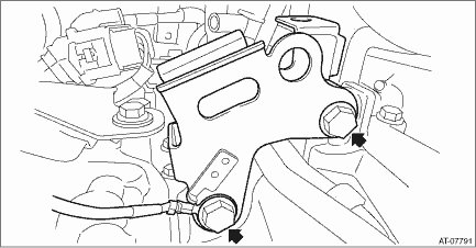
16. Install the air breather hose to the pitching stopper bracket.
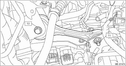
17. Install the pitching stopper.
Tightening torque:
T1: 50 N·m (5.1 kgf-m, 36.9 ft-lb)
T2: 58 N·m (5.9 kgf-m, 42.8 ft-lb)
18. Connect the following harness connectors.
• Transmission harness connectors
• Inhibitor harness connector
• Transmission radio ground terminal
Tightening torque:
13 N·m (1.3 kgf-m, 9.6 ft-lb)
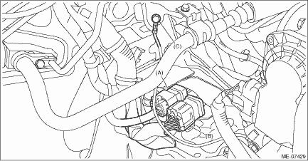
(A) | Transmission harness connectors |
(B) | Inhibitor harness connector |
(C) | Transmission radio ground terminal |
19. Install the air intake boot assembly. Air Intake Boot > INSTALLATION">
20. Adjust the CVTF level. CVTF > ADJUSTMENT">
21. Perform the operation of AT learning mode. Learning Control">
 Removal
CONTINUOUSLY VARIABLE TRANSMISSION(TR580) > Control Valve BodyREMOVALCAUTION:• Directly after the vehicle has been running or the engine has been idling for a long time, the CVTF is hot. Be c ...
 Converter case
...
Other materials:
In-Car-Device setting screen
The Bluetooth settings can be confirmed
and changed.
1. Display the "SETTINGS" screen. Refer
to "Registering a Bluetooth phone for the
first time" F5-65.
2. On the "SETTINGS" screen for "In-
Car-Device setting", select the "Set" key.
Display the Bluetooth device address
of the in ...
Inspection
MANUAL TRANSMISSION AND DIFFERENTIAL(5MT) > Drive Pinion Shaft AssemblyINSPECTIONDisassembled parts should be washed with cleaning solvent first, then inspected carefully.1. BearingReplace the bearings in the following cases.• When the bearing balls, outer races and inner races are broken o ...
Control screen and audio panel
Select to display the audio source
selection screen.
Select to display the play mode
currently selected. Refer to "Select
play mode"
Select to display folder list.
Shows progress.
The tracks in the folder are played
back 10 seconds each from the
beginning of the track.
Sel ...
