Subaru Crosstrek Service Manual: Installation
CLUTCH SYSTEM > Operating Cylinder
INSTALLATION
1. Install in the reverse order of removal.
NOTE:
• Before installing the operating cylinder, apply grease to the contact point of the release lever and operating cylinder.
Grease:
NICHIMOLY N-130 or equivalent
• Be sure to install the clutch hose with the mark side facing upward.
• Be careful not to twist the clutch hose during installation.
• Use a new gasket.
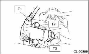
Tightening torque:
T1: 18 N·m (1.8 kgf-m, 13.3 ft-lb)
T2: 37 N·m (3.8 kgf-m, 27.3 ft-lb)
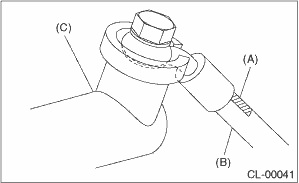
(A) | Mark |
(B) | Clutch hose |
(C) | Operating cylinder |
Tightening torque:
Air intake boot
3 N·m (0.3 kgf-m, 2.2 ft-lb)
2. After bleeding air from the operating cylinder, ensure that the clutch operates properly. Clutch Fluid Air Bleeding">
 Inspection
CLUTCH SYSTEM > Operating CylinderINSPECTION1. Check that the operating cylinder is not damaged. Replace the operating cylinder if it is damaged.2. Check the brake fluid leakage on the operating cy ...

Other materials:
Engine oil pressure Inspection
MECHANICAL(H4DO) > Engine Oil PressureINSPECTION1. Disconnect the ground cable from battery. NOTE">2. Remove the oil pressure switch. Oil Pressure Switch > REMOVAL">3. Install the oil pressure gauge to the chain cover.4. Connect the battery ground terminal. NOTE">5. ...
Dtc p0606 control module processor
ENGINE (DIAGNOSTICS)(H4DO) > Diagnostic Procedure with Diagnostic Trouble Code (DTC)DTC P0606 CONTROL MODULE PROCESSORDTC detecting condition:Immediately at fault recognitionTrouble symptom:• Improper idling• Poor driving performanceCAUTION:After servicing or replacing faulty parts, p ...
Inspection
FRONT SUSPENSION > Front StrutINSPECTIONCheck the removed part for wear, damage and cracks, and then repair or replace it if defective.1. STRUT1. Check for oil leaks.2. Move the piston rod up and down to check that it operates smoothly without any hitch.3. Check the piston rod runout.Preparation ...
