Subaru Crosstrek Service Manual: Installation
CLUTCH SYSTEM > Clutch Disc and Cover
INSTALLATION
1. Insert the ST into the clutch disc and the ST end into pilot bearing to install the clutch disc.
NOTE:
When installing the clutch disc, be careful to attach in the correct direction.
| ST 499747100 | CLUTCH DISC GUIDE |
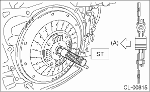
(A) | Flywheel side |
2. Install the clutch cover and tighten the bolts to the specified torque.
NOTE:
• When installing the clutch cover, position the clutch cover so that the spacing between the unbalance marks (paint mark) on the flywheel and clutch cover is 120° or more apart. (The unbalance mark indicates the direction of residual unbalance.)
• Temporarily tighten the bolts by hand. Each bolt should be tightened to the specified torque in a crisscross order.
Tightening torque:
16 N·m (1.6 kgf-m, 11.8 ft-lb)
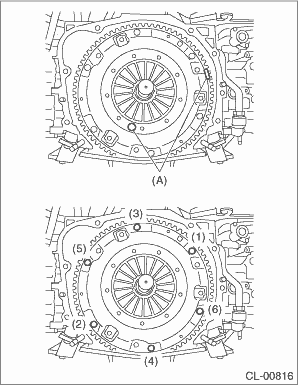
(A) | Unbalance mark (paint) |
3. Remove the ST.
| ST 499747100 | CLUTCH DISC GUIDE |
4. Install the transmission assembly. Manual Transmission Assembly > INSTALLATION">
 Removal
CLUTCH SYSTEM > Clutch Disc and CoverREMOVAL1. Remove the transmission assembly from the vehicle. Manual Transmission Assembly > REMOVAL">2. Attach the ST on the flywheel.ST 499747100 ...
 Clutch fluid
...
Other materials:
Installation
WIPER AND WASHER SYSTEMS > Rear Wiper MotorINSTALLATION1. Install each part in the reverse order of removal.2. Check that the mark on the cap - pivot wiper faces up, as shown in the figure.Tightening torque:Refer to “COMPONENT” of “General Description”. General Descriptio ...
Removal
MECHANICAL(H4DO) > CamshaftREMOVAL1. CAMSHAFT RHThe camshaft RH and cam carrier are designed as removing as a unit. Refer to “Cam Carrier” for removal procedures of camshaft RH. Cam Carrier > REMOVAL"> Cam Carrier > DISASSEMBLY">2. CAMSHAFT LHThe camshaft LH an ...
Remote engine start system Wiring diagram
WIRING SYSTEM > Remote Engine Start SystemWIRING DIAGRAM ...
