Subaru Crosstrek Service Manual: Installation
BRAKE > Stop Light Switch
INSTALLATION
1. BULB TYPE
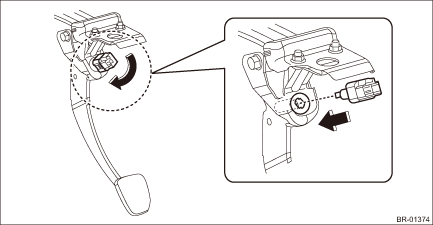
1. Install the stop light switch.
CAUTION:
• Turn the stop light switch clockwise when installing so that it can return backward by approximately 1 mm (0.04 in) and clearance is automatically adjusted.
• If it is hard to turn the switch, reduce the switch pushing force and turn it again.
(1) While pulling up the brake pedal toward you, contact the stop light switch to the stopper and temporarily install it by rotating it clockwise.
(2) Adjust the stop light switch position, and install it. Stop Light Switch > ADJUSTMENT">
(3) Install the stop light switch connector.
2. Install the cover assembly - instrument panel LWR driver.
3. Connect the battery ground terminal.
4. Check that the brake light operate properly.
5. Check the stop light switch operation.
(1) Turn the ignition switch to OFF and connect the Subaru Select Monitor.
(2) Start the engine and warm it up to a sufficient temperature.
NOTE:
Perform the following operations with the engine running.
(3) Display the data of «Brake Switch» and «Pressure Sensor Output» by following the Subaru Select Monitor display screen.
(4) Check that the stop light switch is ON with the brake pedal not depressed.
(5) Quickly depress the brake pedal 5 times.
(6) Slowly release the brake pedal depressed at the fifth time and check that the master cylinder pressure is within the standard value when the stop light switch changes from ON to OFF.
Specification:
Less than 1 Mpa (10 bar)
2. LED TYPE
1. Adjust the stop light switch position, and then secure the stop light switch by turning it clockwise. Stop Light Switch > ADJUSTMENT">
2. Install each part in the reverse order of removal.
3. Check the stop light switch operation.
 Inspection
BRAKE > Stop Light SwitchINSPECTION1. CLEARANCE CHECKNOTE:Check for clearance is applied only to LED model.1. Measure the clearance between the end of the stop light switch and the stopper.Specific ...
 Air bleeding Procedure
BRAKE > Air BleedingPROCEDURECAUTION:• Do not let brake fluid come into contact with the painted surface of the vehicle body. Wash away with water immediately and wipe off if it is spilled by ...
Other materials:
Installation
CONTINUOUSLY VARIABLE TRANSMISSION(TR580) > CVTF Cooler (With Warmer Function)INSTALLATION1. Install the CVTF cooler (with warmer feature) to the transmission.Tightening torque:23 N·m (2.3 kgf-m, 17.0 ft-lb)2. Install the engine coolant inlet hose.NOTE:With the triangle mark on the engine ...
Radiator cap Inspection
COOLING(H4DO) > Radiator CapINSPECTION1. Check that the radiator cap does not have deformation, cracks or damage.2. Attach the radiator cap tester to radiator cap.3. Increase pressure until the radiator cap tester gauge needle stops. Radiator cap is functioning properly if it holds the service li ...
Diagnostics with phenomenon Inspection
AUTO HEADLIGHT BEAM LEVELER SYSTEM (DIAGNOSTICS) > Diagnostics with PhenomenonINSPECTION1. BEAM LEVEL CONTROL DOES NOT FUNCTIONCAUTION:• Before performing diagnosis, check the fuse in this circuit.• Initialization is required after replacing the auto headlight beam leveler CM.Wiring d ...
