Subaru Crosstrek Service Manual: Installation
BRAKE > Brake Booster
INSTALLATION
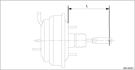
1. Check and adjust the operating rod of the vacuum booster assembly.
(1) Measure the length between the vacuum booster assembly mounting surface and clevis pin hole.
(2) If it is not within the specification, loosen the lock nut, rotate the vacuum booster assembly operating rod to adjust the rod length.
Specification L:
136.3 mm (5.37 in)
2. Install each part in the reverse order of removal.
CAUTION:
• Apply grease to the snap pin to prevent the operating rod from wear.
• Replace the clevis pin with new parts, and apply thin coat of NIGTIGHT LYW No. 2 grease to the clevis pin.
• When installing the master cylinder assembly, replace the seal sub assembly with a new part, and install it to the vacuum booster assembly.
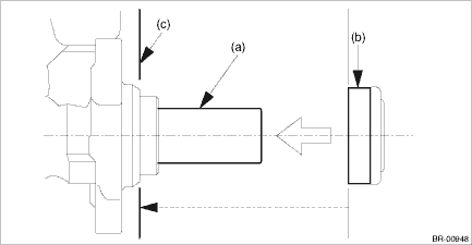
(a) | Primary piston | (b) | Seal sub ASSY | (c) | Install the seal sub ASSY to this surface. |
Tightening torque:
Vacuum booster assembly: 18 N·m (1.84 kgf-m, 13.3 ft-lb)
Master cylinder assembly: 13 N·m (1.33 kgf-m, 9.6 ft-lb)
Brake pipe flare nut: 19 N·m (1.94 kgf-m, 14.0 ft-lb)
Operating lock nut: 22 N·m (2.24 kgf-m, 16.2 ft-lb)
Knee airbag module: 7.5 N·m (0.76 kgf-m, 5.5 ft-lb)
3. Install the air conditioner pipe. General Description > COMPONENT">
4. Charge refrigerant. Refrigerant Charging Procedure > PROCEDURE">
5. Bleed air from the brake system. Air Bleeding > PROCEDURE">
6. Perform a road test to make sure the brakes do not drag.
 Removal
BRAKE > Brake BoosterREMOVALCAUTION:• Do not allow brake fluid to come in contact with the painted surface of the vehicle body. If it does, wash off with water and wipe away completely.• ...
 Brake fluid
...
Other materials:
Dtc b1827 short in side airbag lh (to ground)
AIRBAG SYSTEM (DIAGNOSTICS) > Diagnostic Chart with Trouble CodeDTC B1827 SHORT IN SIDE AIRBAG LH (TO GROUND)Diagnosis start condition:Ignition voltage is 10 V to 16 V.DTC detecting condition:• Side airbag harness (LH) circuit is shorted to ground.• Side airbag module (LH) is faulty.& ...
Fuel gauge
Fuel gauge (type A)
Trip knob
Fuel gauge (type B)
Trip knob (U.S.-spec. models)
Trip knob (except U.S.-spec. models)
The fuel gauge is displayed when the
ignition is in the "ON" position, and it
shows the approximate amount of fuel
remaining in the tank.
The gauge indic ...
Wiring diagram
SECURITY AND LOCKS > Door Lock Control SystemWIRING DIAGRAMFor wiring diagrams related to the door lock control system, refer to the following items.• Keyless entry system: Keyless Entry System > WIRING DIAGRAM">• Keyless access system: Keyless Access System > WIRING D ...
