Subaru Crosstrek Service Manual: Inspection
Blind Spot Detection/Rear Cross Traffic Alert (DIAGNOSTICS) > Subaru Select Monitor
INSPECTION
1. COMMUNICATION FOR INITIALIZING IMPOSSIBLE
When communication with the radar sensor is impossible
Detecting condition:
• Defective harness connector
• Power supply circuit malfunction
• Defective radar sensor
• Defective CAN communication circuit
• Defective Subaru Select Monitor
Trouble symptom:
Communication is impossible between radar sensor and Subaru Select Monitor.
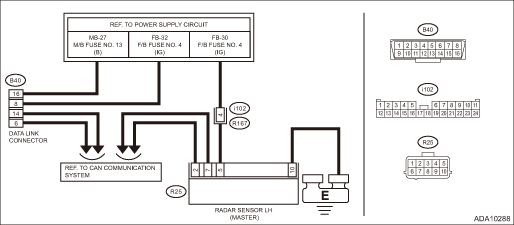
Wiring diagram:
BSD/RCTA system Blind Spot Detection/Rear Cross Traffic Alert > WIRING DIAGRAM">
| STEP | CHECK | YES | NO |
1.CHECK FUSE.
1) Turn the ignition switch to OFF.
2) Check the fuse for radar sensor LH. Relay and Fuse">
Is it normal?
Subaru Select Monitor > INSPECTION">Go to Step 2.
Replace the fuse. If the replaced fuse has blown out immediately, repair the short circuit to ground in harness between fuse and radar sensor LH.
2.CHECK HARNESS (OPEN CIRCUIT).
1) Disconnect the radar sensor LH connector.
2) Turn the ignition switch to ON.
3) Using a tester, measure the voltage between radar sensor LH connector (harness side) and chassis ground.
Connector & terminal
(R25) No. 5 (+) — Chassis ground (−):
Is the voltage 10 V or more?
Subaru Select Monitor > INSPECTION">Go to Step 3.
Repair the open circuit of harness between fuse and radar sensor LH connector.
3.CHECK HARNESS (OPEN CIRCUIT).
1) Turn the ignition switch to OFF.
2) Using a tester, measure the resistance between radar sensor LH connector (harness side) and chassis ground.
Connector & terminal
(R25) No. 10 — Chassis ground:
Is the resistance less than 1 ??
Subaru Select Monitor > INSPECTION">Go to Step 4.
Repair the open circuit in harness between radar sensor and chassis ground.
4.CHECK LAN SYSTEM.
1) Connect the radar sensor LH connector.
2) Inspect LAN system. Basic Diagnostic Procedure">
Is it normal?
Subaru Select Monitor > INSPECTION">Go to Step 5.
Perform the inspection according to the diagnosis for LAN system.
5.CHECK RADAR SENSOR.
Communicate with the radar sensor.
Is communication possible?
The circuit has returned to a normal condition at this time. Reproduce the failure, and then perform the diagnosis again.
NOTE:
In this case, temporary poor contact of connector, temporary open or short circuit of harness may be the cause.
Replace the radar sensor LH. Radar Sensor">

 Operation
Blind Spot Detection/Rear Cross Traffic Alert (DIAGNOSTICS) > Subaru Select MonitorOPERATION• For detailed operation procedures, refer to “Application help”.• When the radar ...
Other materials:
Inspection
LIGHTING SYSTEM > Door SwitchINSPECTION1. Check the resistance between switch terminals.Preparation tool:Circuit testerTerminal No.Inspection conditionsStandardConnection diagram1 — 3When door is openedLess than 1 ?When door is closed1 M? or more2. Replace the switch assembly - door if the insp ...
Remote keyless entry system
CAUTION
Do not expose the remote transmitter
to severe shocks, such as
those experienced as a result of
dropping or throwing.
Do not take the remote transmitter
apart except when replacing
the battery
Do not get the remote transmitter
wet. If it gets wet, wipe it dry with
a clo ...
Inspection
LIGHTING SYSTEM > Light Control SensorINSPECTION1. Turn the ignition switch to ON.2. Set the lighting switch to AUTO position.3. Check the voltage between the sensor terminals.Preparation tool:Circuit testerTerminal No.Inspection conditionsStandardConnection diagram2 (+) — 1 (−)Measure th ...
