Subaru Crosstrek Service Manual: Inspection
AUTO HEADLIGHT BEAM LEVELER SYSTEM (DIAGNOSTICS) > Subaru Select Monitor
INSPECTION
1. COMMUNICATION FOR INITIALIZING IMPOSSIBLE
Communication error with auto headlight beam leveler CM
Detecting condition:
• Defective harness connector
• Power supply circuit malfunction
• Defective auto headlight beam leveler CM
• Defective CAN communication circuit
• Defective Subaru Select Monitor
Trouble symptom:
Communication is impossible between auto headlight beam leveler CM and Subaru Select Monitor.
CAUTION:
Initialization is required after replacing the auto headlight beam leveler CM.
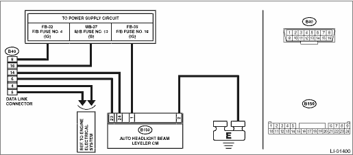
Wiring diagram:
Headlight beam leveler system Headlight Beam Leveler System > WIRING DIAGRAM">
| STEP | CHECK | YES | NO |
1.CHECK OTHER COMMUNICATION.
Communicate with the system other than the auto headlight beam leveler CM using the Subaru Select Monitor.
Is the communication to other control module possible?
Subaru Select Monitor > INSPECTION">Go to Step 2.
Perform the “Communication for Initializing Impossible” of LAN system. Subaru Select Monitor > COMMUNICATION FOR INITIALIZING IMPOSSIBLE">
2.CHECK LAN SYSTEM.
Inspect LAN system. Basic Diagnostic Procedure > PROCEDURE">
Is there any fault?
Perform the inspection according to the diagnosis for LAN system.
Subaru Select Monitor > INSPECTION">Go to Step 3.
3.CHECK FOR POOR CONTACT.
1) Turn the ignition switch to OFF.
2) Disconnect the auto headlight beam leveler CM connector.
3) Connect the disconnected connectors.
4) Communicate with the auto headlight beam leveler CM using the Subaru Select Monitor.
Is communication possible?
It is possible that temporary poor communication occurs.
Replace the auto headlight beam leveler CM. Auto Headlight Beam Leveler Control Module">

 Operation
AUTO HEADLIGHT BEAM LEVELER SYSTEM (DIAGNOSTICS) > Subaru Select MonitorOPERATION• For detailed operation procedures, refer to “Application help”.• If the auto headlight bea ...
Other materials:
When starting the engine
To start the engine with remote engine
start system, briefly press the lock button
twice within 2 seconds, then press and
hold the lock button for 3 seconds.
1. Press the lock button briefly. The
hazard warning flashers then flash once
and the keyless buzzer chirps once.
2. Within 2 secon ...
Dtc u0428 invalid data received from steering angle sensor module
LAN SYSTEM (DIAGNOSTICS) > Diagnostic Procedure with Diagnostic Trouble Code (DTC)DTC U0428 INVALID DATA RECEIVED FROM STEERING ANGLE SENSOR MODULEDTC DETECTING CONDITION:Defective data was transmitted from steering angle sensor.TROUBLE SYMPTOM:VDC CM does not operate normally.STEPCHECKYESNO1.CHE ...
Precautions in trouble diagnosis and repair of electric parts
WIRING SYSTEM > Working PrecautionsPRECAUTIONS IN TROUBLE DIAGNOSIS AND REPAIR OF ELECTRIC PARTS1. The battery cable must be disconnected from the battery’s (−) terminal, and the ignition switch must be set to the OFF position, unless otherwise required by the diagnostics.2. Securely ...
