Subaru Crosstrek Service Manual: Inspection
VEHICLE DYNAMICS CONTROL (VDC) > VDC Control Module and Hydraulic Control Unit (VDCCM&H/U)
INSPECTION
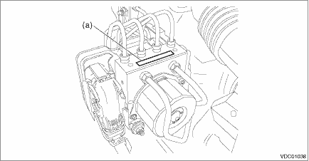
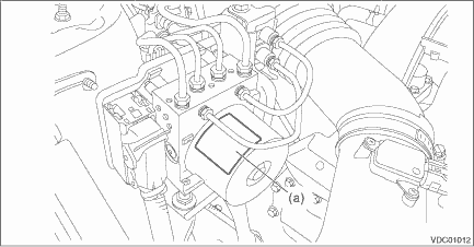
1. Check the identification (a) of the VDC control module & hydraulic control unit (VDCCM&H/U).
NOTE:
For the identification, refer to “SPECIFICATION” in “General Description”. General Description > SPECIFICATION">
• Models without EyeSight
• Models with EyeSight
2. Check the condition of connection and settlement of connector, and correct or replace if defective.
1. CHECKING THE HYDRAULIC UNIT ABS OPERATION BY PRESSURE GAUGE
1. Lift up the vehicle, and then remove the wheel.
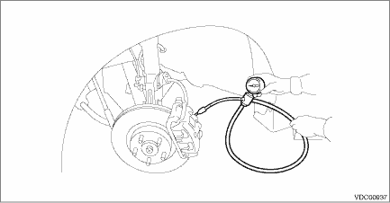
2. Remove the bleeder - screws from the FL and FR caliper bodies.
3. Connect two pressure gauges to FL and FR caliper bodies.
CAUTION:
• Use a pressure gauge used exclusively for brake fluid measurement.
• Do not use the pressure gauge used for the measurement of transmission oil. Doing so will cause the piston seal to expand and deform.
NOTE:
Wrap sealing tape around the pressure gauge.
4. Bleed air from the pressure gauges and the FL and FR caliper bodies.
5. Perform ABS sequence control. ABS Sequence Control">
NOTE:
When the hydraulic unit begins to work, first the FL side performs decompression, hold and compression, and then the FR side performs decompression, hold and compression.
6. Read values indicated on the pressure gauge and check if the fluctuation of the values between decompression and compression meets the standard values. Depress the brake pedal and check that the kick-back is normal, and tightness is normal.
Inspection conditions | Front wheel | Rear wheel |
Initial value | 3,500 kPa (36 kgf/cm2, 511 psi) | 3,500 kPa (36 kgf/cm2, 511 psi) |
When depressurized | 500 kPa (5 kgf/cm2, 73 psi) or less | 500 kPa (5 kgf/cm2, 73 psi) or less |
When pressurized | 3,500 kPa (36 kgf/cm2, 511 psi) or more | 3,500 kPa (36 kgf/cm2, 511 psi) or more |
7. Disconnect the pressure gauges from FL and FR caliper bodies.
8. Install the bleeder - screws of the FL and FR caliper bodies.
9. Remove the bleeder - screws from the RL and RR caliper bodies.
10. Connect two pressure gauges to RL and RR caliper bodies.
11. Bleed air from RL and RR caliper bodies, and pressure gauge.
12. Perform ABS sequence control. ABS Sequence Control">
NOTE:
When the hydraulic unit begins to work, first the RR side performs decompression, hold and compression, and then the RL side performs decompression, hold and compression.
13. Read values indicated on the pressure gauge and check if the fluctuation of the values between decompression and compression meets specification. Depress the brake pedal and check that the kick-back is normal, and tightness is normal.
14. Disconnect the pressure gauge from the RL and RR caliper bodies.
15. Install the bleeder - screws of the RL and RR caliper bodies.
16. Bleed air from the brake system. Air Bleeding">
2. CHECKING THE HYDRAULIC UNIT ABS OPERATION WITH THE BRAKE TESTER
1. Set wheels other than the one to measure on free rollers.
2. Prepare for the ABS sequence control operation. ABS Sequence Control">
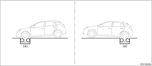
3. Set the front wheels or rear wheels on the brake tester (a) and set the gear to neutral.
4. Operate the brake tester.
5. Perform ABS sequence control. ABS Sequence Control">
6. When the hydraulic unit begins to work, check the following work sequence.
(1) The FL wheel performs decompression, hold and compression in sequence, and subsequently the FR wheel repeats the cycle.
(2) The RR wheel performs decompression, hold and compression in sequence, and subsequently the RL wheel repeats the cycle.
7. Read values indicated on the brake tester and check if the fluctuation of the values between decompression and compression meets specification.
Inspection conditions | Front wheel | Rear wheel |
Initial value | 1,000 N (102 kgf, 225 lb) | 1,000 N (102 kgf, 225 lb) |
When depressurized | 500 N (51 kgf, 112 lb) or less | 500 N (51 kgf, 112 lb) or less |
When pressurized | 1,000 N (102 kgf, 225 lb) or more | 1,000 N (102 kgf, 225 lb) or more |
8. After the inspection, depress the brake pedal and check that it is not abnormally hard, and tightness is normal.
3. CHECKING THE HYDRAULIC UNIT VDC OPERATION USING A PRESSURE GAUGE
1. Lift up the vehicle, and then remove the wheel.
2. Remove the bleeder - screws from the FL and FR caliper bodies.
3. Connect two pressure gauges to FL and FR caliper bodies.
CAUTION:
• Use a pressure gauge used exclusively for brake fluid measurement.
• Do not use a pressure gauge used for the measuring transmission oil pressure, as the piston seal may expand and deform.
NOTE:
Wrap sealing tape around the pressure gauge.
4. Bleed air from the pressure gauge.
5. Perform VDC sequence control. VDC Sequence Control">
NOTE:
When the hydraulic unit begins to work, first the FL side performs compression, hold, and decompression, and then the FR side performs compression, hold, and decompression.
6. Read values indicated on the pressure gauge and check if the fluctuation of the values between decompression and compression meets specification. Depress the brake pedal and check that it is not abnormally hard, and tightness is normal.
Inspection conditions | Front wheel | Rear wheel |
When pressurized | 3,000 kPa (31 kgf/cm2, 441 psi) or more | 3,000 kPa (31 kgf/cm2, 441 psi) or more |
When depressurized | 500 kPa (5 kgf/cm2, 73 psi) or less | 500 kPa (5 kgf/cm2, 73 psi) or less |
7. Disconnect the pressure gauges from FL and FR caliper bodies.
8. Install the bleeder - screws of the FL and FR caliper bodies.
9. Remove the bleeder - screws from the RL and RR caliper bodies.
10. Connect two pressure gauges to RL and RR caliper bodies.
11. Bleed air from RL and RR caliper bodies, and pressure gauge.
12. Perform VDC sequence control. VDC Sequence Control">
NOTE:
When the hydraulic unit begins to work, first the RR side performs compression, hold, and decompression, and then the RL side performs compression, hold, and decompression.
13. Read the values indicated on the pressure gauges and check if it is within specification. Depress the brake pedal and check that it is not abnormally hard, and tightness is normal.
14. Disconnect the pressure gauge from the RL and RR caliper bodies.
15. Install the bleeder - screws of the RL and RR caliper bodies.
16. Bleed air from the brake system. Air Bleeding">
4. CHECK HYDRAULIC UNIT VDC OPERATION WITH BRAKE TESTER
1. Set wheels other than the one to measure on free rollers.
2. Prepare to operate the VDC sequence control. VDC Sequence Control">
3. Set the front wheels or rear wheels on the brake tester (a) and set the gear to neutral.
4. Operate the brake tester.
5. Perform VDC sequence control. VDC Sequence Control">
6. When the hydraulic unit begins to work, check the following work sequence.
(1) The FL wheel performs compression, hold and decompression in sequence, and subsequently the FR wheel repeats the cycle.
(2) The RR wheel performs compression, hold and decompression in sequence, and subsequently the RL wheel repeats the cycle.
7. Read values indicated on the brake tester and check if the fluctuation of the values between decompression and compression meets specification.
Inspection conditions | Front wheel | Rear wheel |
When pressurized | 2,000 N (204 kgf, 450 lbf) or more | 2,000 N (204 kgf, 450 lbf) or more |
When depressurized | 500 N (51 kgf, 112 lbf) or less | 500 N (51 kgf, 112 lbf) or less |
8. After the inspection, depress the brake pedal and check that it is not abnormally hard, and tightness is normal.
 Replacement
VEHICLE DYNAMICS CONTROL (VDC) > VDC Control Module and Hydraulic Control Unit (VDCCM&H/U)REPLACEMENT1. ONLY FOR MODELS WITHOUT EyeSightCAUTION:• Because the pressure sensor built into th ...
 Installation
VEHICLE DYNAMICS CONTROL (VDC) > VDC Control Module and Hydraulic Control Unit (VDCCM&H/U)INSTALLATION1. MODELS WITHOUT EyeSightCAUTION:• When installing the VDCCM&H/U to the bracket ...
Other materials:
Removal
CONTROL SYSTEMS > Select CableREMOVAL1. Shift the select lever to “N” range.2. Disconnect the ground cable from battery. NOTE">NOTE:For model with battery sensor, disconnect the ground terminal from battery sensor.3. Lift up the vehicle.4. Remove the center exhaust pipe. Cen ...
Subaru select monitor Operation
CRUISE CONTROL SYSTEM (DIAGNOSTICS) > Subaru Select MonitorOPERATION1. GENERAL DESCRIPTIONThe on-board diagnosis function of the cruise control system uses Subaru Select Monitor.The on-board diagnosis function operates in two categories, which are used depending on the type of problems;1. Cruise ...
Screen Settings
After entering the "Screen Settings" menu,
select one of the following menus.
Welcome Good-bye Screen
The welcome screen/good-bye screens
can be activated or deactivated. Select
"On" to activate the screens. Select "Off"
to deactivate the screens.
Gauge Initial Movement
The movement of the m ...
