Subaru Crosstrek Service Manual: Inspection
LIGHTING SYSTEM > Turn Signal Light & Hazard Light Unit
INSPECTION
1. Disconnect the connector of the turn signal & hazard unit.
2. Measure the voltage between the turn signal & hazard unit connector and the chassis ground.
Preparation tool:
Circuit tester
Terminal No. | Inspection conditions | Standard | Connection diagram |
4 (+) — Chassis ground (−) | Always | 10 — 14 V |
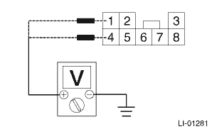
1 (+) — Chassis ground (−)
IG OFF > ON
Less than 1 V > 10 — 14 V
Repair or replace the harness if the inspection result is not within the standard value.
3. Measure the resistance between the turn signal & hazard unit connector and the chassis ground.
Terminal No. | Inspection conditions | Standard | Connection diagram |
7 — Chassis ground | Always | Less than 1 ? |
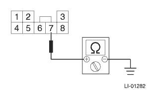
Repair or replace the harness if the inspection result is not within the standard value.
4. Connect the turn signal & hazard unit connector.
5. Measure the voltage between turn signal & hazard unit and chassis ground.
Terminal No. | Input/Output | Inspection conditions | Standard |
6 (+) — Chassis ground (−) | Input | Turn signal switch (right) OFF > ON | 9 V or more > less than 1 V |
5 (+) — Chassis ground (−) | Input | Turn signal switch (left) OFF > ON | 9 V or more > less than 1 V |
8 (+) — Chassis ground (−) | Input | Hazard switch OFF > ON | 9 V or more > less than 1 V |
2 (+) — Chassis ground (−) | Output | Turn signal switch (right) OFF > ON | Repeat less than 1 V > less than 1 V ←> more than 9 V at 60 to 120 times per minute. |
3 (+) — Chassis ground (−) | Output | Turn signal switch (left) OFF > ON | Repeat less than 1 V > less than 1 V ←> more than 9 V at 60 to 120 times per minute. |
2 (+) — Chassis ground (−) | Output | Hazard switch OFF > ON | Repeat less than 1 V > less than 1 V ←> more than 9 V at 60 to 120 times per minute. |
3 (+) — Chassis ground (−) | Output | Hazard switch OFF > ON | Repeat less than 1 V > less than 1 V ←> more than 9 V at 60 to 120 times per minute. |
Replace the turn signal & hazard unit if the inspection result is not within the standard value.

 Removal
LIGHTING SYSTEM > Turn Signal Light & Hazard Light UnitREMOVALCAUTION:Before handling the airbag system components, refer to “CAUTION” of “General Description” in &ldquo ...
Other materials:
Dtc b16f2 front sub sensor rh recognition error
AIRBAG SYSTEM (DIAGNOSTICS) > Diagnostic Chart with Trouble CodeDTC B16F2 FRONT SUB SENSOR RH RECOGNITION ERRORDiagnosis start condition:Ignition voltage is 10 V to 16 V.DTC detecting condition:Front sub sensor (RH) is misinstalled.CAUTION:Before performing diagnosis, refer to “CAUTION&rdqu ...
Dtc u0100 lost communication with ecm/pcm a
CONTINUOUSLY VARIABLE TRANSMISSION (DIAGNOSTICS) > Diagnostic Procedure with Diagnostic Trouble Code (DTC)DTC U0100 LOST COMMUNICATION WITH ECM/PCM “A”NOTE:Refer to “LAN SYSTEM (DIAGNOSTICS)” for diagnostic procedures. Basic Diagnostic Procedure">1. OUTLINE OF DIA ...
Dtc p0851 park/neutral switch input circuit low
ENGINE (DIAGNOSTICS)(H4DO) > Diagnostic Procedure with Diagnostic Trouble Code (DTC)DTC P0851 PARK/NEUTRAL SWITCH INPUT CIRCUIT LOW1. AT MODELDTC detecting condition:Detected when two consecutive driving cycles with fault occur.Trouble symptom:Improper idlingCAUTION:After servicing or replacing f ...
