Subaru Crosstrek Service Manual: Inspection
LAN SYSTEM (DIAGNOSTICS) > CAN Communication Circuit Check
INSPECTION
1. GROUND SHORT INSPECTION
Wiring diagram:
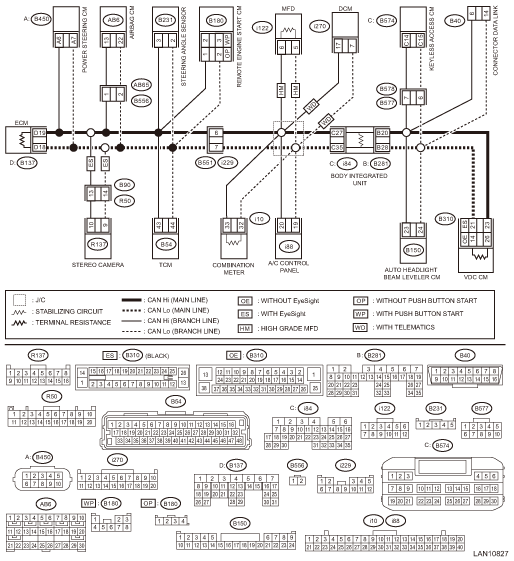
CAN communication system CAN Communication System > WIRING DIAGRAM">
• Without BSD/RCTA
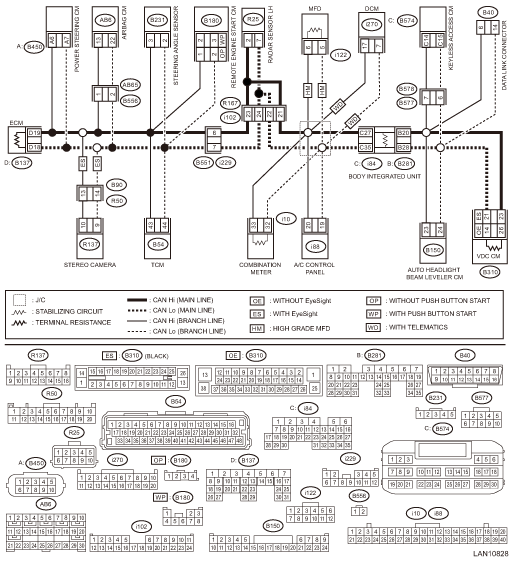
• With BSD/RCTA
NOTE:
Main wiring harness or related lines may be shorted to ground, or shorted to ground in one of the control modules.
| STEP | CHECK | YES | NO |
1.CHECK BETWEEN RELATED LINES AND MAIN WIRING HARNESS.
Using the tester, measure the resistance between terminals.
Connector & terminal
(B40) No. 6 — Chassis ground:
(B40) No. 14 — Chassis ground:
Is the resistance less than 10 ??
CAN Communication Circuit Check > INSPECTION">Go to Step 2.
Currently, it is normal.
2.CHECK CONTROL MODULE.
With the tester connected, disconnect control module.
NOTE:
Disconnect the body integrated unit at the end.
Connector & terminal
(B40) No. 6 — Chassis ground:
(B40) No. 14 — Chassis ground:
Did the resistance change to 10 ? or more?
Replace the control module whose resistance has changed. When the value changed at disconnecting the body integrated unit,
CAN Communication Circuit Check > INSPECTION">Go to Step 3.
Repair or replace the short circuit of the main wiring harness and related lines between body integrated unit and VDC CM.
3.CHECK BETWEEN MAIN WIRING HARNESSES.
Using the tester, measure the resistance between terminals.
Connector & terminal
(i84) No. 27 — Chassis ground:
(i84) No. 35 — Chassis ground:
Is the resistance less than 10 ??
Repair or replace the short circuit of the main wiring harness and related lines between ECM and body integrated unit.
Replace the body integrated unit. Body Integrated Unit">
2. BATTERY SHORT INSPECTION
Wiring diagram:
CAN communication system CAN Communication System > WIRING DIAGRAM">
• Without BSD/RCTA
• With BSD/RCTA
NOTE:
Main wiring harness or related lines may be shorted to battery circuit, or shorted to battery circuit in one of the control modules.
| STEP | CHECK | YES | NO |
1.CHECK BETWEEN RELATED LINES AND MAIN WIRING HARNESS.
1) Turn the ignition switch to ON.
2) Using the tester, measure the voltage between terminals.
Connector & terminal
(B40) No. 6 — Chassis ground:
(B40) No. 14 — Chassis ground:
Is the voltage 5 V or less?
Currently, it is normal.
CAN Communication Circuit Check > INSPECTION">Go to Step 2.
2.CHECK CONTROL MODULE.
With the tester connected, disconnect control module.
NOTE:
Disconnect the body integrated unit at the end.
Connector & terminal
(B40) No. 6 — Chassis ground:
(B40) No. 14 — Chassis ground:
Did the voltage change to 5 V or less?
Replace the control module whose voltage has changed. When the value changed at disconnecting the body integrated unit,
CAN Communication Circuit Check > INSPECTION">Go to Step 3.
Repair or replace the short circuit of the harness between body integrated unit and VDC CM.
3.CHECK BETWEEN MAIN WIRING HARNESSES.
Using the tester, measure the voltage between terminals.
Connector & terminal
(i84) No. 27 — Chassis ground:
(i84) No. 35 — Chassis ground:
Is the voltage 5 V or less?
Replace the body integrated unit. Body Integrated Unit">
Repair or replace the short circuit of the harness between ECM and body integrated unit.
3. 53 — 61 ?
Wiring diagram:
CAN communication system CAN Communication System > WIRING DIAGRAM">
• Without BSD/RCTA
• With BSD/RCTA
NOTE:
When the measured resistance value is 53 — 61 ?, main wiring harness or related lines may be shorted to ground, or shorted to power supply line, or related line may be open.
| STEP | CHECK | YES | NO |
1.CHECK BETWEEN RELATED LINES AND MAIN WIRING HARNESS.
Using the tester, measure the resistance between terminals.
Connector & terminal
(B40) No. 6 — Chassis ground:
(B40) No. 14 — Chassis ground:
Is the resistance less than 10 ??
CAN Communication Circuit Check > INSPECTION">Go to Step 2.
CAN Communication Circuit Check > INSPECTION">Go to Step 4.
2.CHECK CONTROL MODULE.
With the tester connected, disconnect control module.
NOTE:
Disconnect the body integrated unit at the end.
Connector & terminal
(B40) No. 6 — Chassis ground:
(B40) No. 14 — Chassis ground:
Did the resistance change to 10 ? or more?
Replace the control module whose resistance has changed. When the value changed at disconnecting the body integrated unit,
CAN Communication Circuit Check > INSPECTION">Go to Step 3.
Repair or replace the short circuit of the harness between body integrated unit and VDC CM.
3.CHECK MAIN WIRING HARNESS AND RELATED LINES.
Using the tester, measure the resistance between terminals.
Connector & terminal
(i84) No. 27 — Chassis ground:
(i84) No. 35 — Chassis ground:
Is the resistance less than 10 ??
Repair or replace the short circuit of the harness between ECM and body integrated unit.
Replace the body integrated unit. Body Integrated Unit">
4.CHECK BETWEEN RELATED LINES AND MAIN WIRING HARNESS.
1) Turn the ignition switch to ON.
2) Using the tester, measure the voltage between terminals.
Connector & terminal
(B40) No. 6 — Chassis ground:
(B40) No. 14 — Chassis ground:
Is the voltage 5 V or less?
CAN communication circuit is normal.
CAN Communication Circuit Check > INSPECTION">Go to Step 5.
5.CHECK CONTROL MODULE.
With the tester connected, disconnect control module.
NOTE:
Disconnect the body integrated unit at the end.
Connector & terminal
(B40) No. 6 — Chassis ground:
(B40) No. 14 — Chassis ground:
Did the voltage change to 5 V or less?
Replace the control module whose voltage has changed. When the value changed at disconnecting the body integrated unit,
CAN Communication Circuit Check > INSPECTION">Go to Step 6.
Repair or replace the short circuit of the harness between body integrated unit and VDC CM.
6.CHECK HARNESS.
Using a tester, measure the voltage between terminals and chassis ground.
Connector & terminal
(i84) No. 27 — Chassis ground:
(i84) No. 35 — Chassis ground:
Is the voltage 5 V or less?
Replace the body integrated unit. Body Integrated Unit">
Repair or replace the short circuit of the harness between ECM and body integrated unit.
4. 52 ? OR LESS
Wiring diagram:
CAN communication system CAN Communication System > WIRING DIAGRAM">
• Without BSD/RCTA
• With BSD/RCTA
NOTE:
When the bus line is measured, combined resistance of end resistance (120 ?) in ECM and end resistance (120 ?) in VDC CM can be measured. The combined resistance is approximately 53 — 61 ? with the stabilizing circuit included. When the measured resistance value is 52 ? or less, main wiring harness or related lines may be shorted, or combined resistance may have changed because resistance other than end resistance is created on the circuit.
| STEP | CHECK | YES | NO |
1.CHECK BETWEEN RELATED LINES AND MAIN WIRING HARNESS.
Using the tester, measure the resistance between terminals.
Connector & terminal
(B40) No. 6 — No. 14:
Is the resistance less than 10 ??
CAN Communication Circuit Check > INSPECTION">Go to Step 2.
CAN Communication Circuit Check > INSPECTION">Go to Step 4.
2.CHECK MAIN WIRING HARNESS AND RELATED LINES.
With a tester connected, disconnect control module connectors in order.
NOTE:
Disconnect the body integrated unit at the end.
Connector & terminal
(B40) No. 6 — No. 14:
Is there any control module whose condition has changed from short state?
Replace the control module whose resistance has changed. When the value changed at disconnecting the body integrated unit,
CAN Communication Circuit Check > INSPECTION">Go to Step 3.
Repair or replace the short circuit of the harness between body integrated unit and VDC CM.
3.CHECK BETWEEN MAIN WIRING HARNESSES.
Using the tester, measure the resistance between terminals.
Connector & terminal
(i84) No. 27 — No. 35:
Is the resistance less than 10 ??
Repair or replace the short circuit of the harness between ECM and body integrated unit.
Replace the body integrated unit. Body Integrated Unit">
4.CHECK CONTROL MODULE.
1) Disconnect ECM and VDC CM connectors.
2) Using a tester, measure the resistance between control module terminals.
Connector & terminal
(B137) No. 18 — No. 19:
(B310) No. 14 — No. 26 (without EyeSight):
(B310) No. 21 — No. 23 (with EyeSight):
Is the resistance 114 — 126 ??
CAN Communication Circuit Check > INSPECTION">Go to Step 5.
Replace the control module whose end resistance value is out of the specified range.
5.CHECK CONTROL MODULE.
1) Disconnect the connector of body integrated unit.
2) Using a tester, measure the resistance between control module terminals.
Connector & terminal
(B281) No. 28 — (i84) No. 27:
(B281) No. 20 — (i84) No. 35:
Is the resistance 2850 — 3150 ??
CAN Communication Circuit Check > INSPECTION">Go to Step 6.
Replace the body integrated unit. Body Integrated Unit">
6.CHECK CONTROL MODULE.
Using a tester, measure the resistance between control module terminals.
Connector & terminal
(B281) No. 28 — (i84) No. 35:
(B281) No. 20 — (i84) No. 27:
Is the resistance less than 1 ??
CAN Communication Circuit Check > INSPECTION">Go to Step 7.
Replace the body integrated unit. Body Integrated Unit">
7.CHECK CONTROL MODULE.
1) Disconnect the combination meter connector.
2) Using a tester, measure the resistance between control module terminals.
Connector & terminal
(i10) No. 32 — No. 33:
Is the resistance 2850 — 3150 ??
CAN Communication Circuit Check > INSPECTION">Go to Step 8.
Replace the combination meter. Combination Meter">
8.CHECK CONTROL MODULE (ONLY FOR MODELS WITH HIGH GRADE MFD).
1) Disconnect the MFD connector.
2) Using a tester, measure the resistance between control module terminals.
Connector & terminal
(i122) No. 5 — No. 6:
Is the resistance 2850 — 3150 ??
CAN Communication Circuit Check > INSPECTION">Go to Step 9.
Replace the MFD. Multi-function Display (MFD)">
9.CHECK HARNESS.
Using the tester, check the short circuit of each harness.
Connector & terminal
(B281) No. 28 — No. 20:
Is the resistance 1 M? or more?
CAN Communication Circuit Check > INSPECTION">Go to Step 11.
CAN Communication Circuit Check > INSPECTION">Go to Step 10.
10.CHECK CONTROL MODULE.
With a tester connected, disconnect control modules in order.
Connector & terminal
(B281) No. 28 — No. 20:
Are there any control modules whose resistance changed to 1 M? or more?
Replace the control module that has changed.
Repair or replace the harness part which has resistance component.
11.CHECK CONTROL MODULE.
With a tester connected, disconnect control modules in order.
Connector & terminal
(i84) No. 27 — No. 35:
Is there any control module whose resistance has changed to 1 M? or more?
Replace the control module that has changed.
Repair or replace the harness part which has resistance component.
5. 62 ? OR MORE
Wiring diagram:
CAN communication system CAN Communication System > WIRING DIAGRAM">
• Without BSD/RCTA
• With BSD/RCTA
NOTE:
When CAN communication circuit is measured, combined resistance of end resistance (120 ?) in ECM and end resistance (120 ?) in VDC CM can be measured. The combined resistance is approximately 53 — 61 ? with the stabilizing circuit included. When the measured resistance value is 62 ? or more, either one of the end resistances, or stabilizing circuit, or main wiring harness may have malfunction such as open circuit.
| STEP | CHECK | YES | NO |
1.CHECK CONTROL MODULE.
1) Disconnect ECM and VDC CM connectors.
2) Using a tester, measure the resistance between control module terminals.
Connector & terminal
(B137) No. 18 — No. 19:
(B310) No. 14 — No. 26 (without EyeSight):
(B310) No. 21 — No. 23 (with EyeSight):
Is the resistance 114 — 126 ??
CAN Communication Circuit Check > INSPECTION">Go to Step 2.
Replace the control module whose value is out of the specification.
2.CHECK CONTROL MODULE.
1) Disconnect the connector of body control module.
2) Using a tester, measure the resistance between control module terminals.
Connector & terminal
(B281) No. 28 — (i84) No. 27:
(B281) No. 20 — (i84) No. 35:
Is the resistance 2850 — 3150 ??
CAN Communication Circuit Check > INSPECTION">Go to Step 3.
Replace the body integrated unit. Body Integrated Unit">
3.CHECK CONTROL MODULE.
Using the tester, measure the resistance between terminals.
Connector & terminal
(B281) No. 28 — (i84) No. 35:
(B281) No. 20 — (i84) No. 27:
Is the resistance less than 1 ??
CAN Communication Circuit Check > INSPECTION">Go to Step 4.
Replace the body integrated unit. Body Integrated Unit">
4.CHECK CONTROL MODULE.
1) Disconnect the combination meter connector.
2) Using a tester, measure the resistance between control module terminals.
Connector & terminal
(i10) No. 32 — No. 33:
Is the resistance 2850 — 3150 ??
CAN Communication Circuit Check > INSPECTION">Go to Step 5.
Replace the combination meter. Combination Meter > REMOVAL">
5.CHECK CONTROL MODULE (ONLY FOR MODELS WITH HIGH GRADE MFD).
1) Disconnect the MFD connector.
2) Using a tester, measure the resistance between control module terminals.
Connector & terminal
(i122) No. 5 — No. 6:
Is the resistance 2850 — 3150 ??
CAN Communication Circuit Check > INSPECTION">Go to Step 6.
Replace the MFD. Multi-function Display (MFD) > REMOVAL">
6.CHECK HARNESS.
Using a tester, check continuity between terminals.
Connector & terminal
(B40) No. 6 — (B310) No. 26 (without EyeSight):
(B40) No. 14 — (B310) No. 14 (without EyeSight):
(B40) No. 6 — (B310) No. 23 (with EyeSight):
(B40) No. 14 — (B310) No. 21 (with EyeSight):
(B40) No. 6 — (B281) No. 20:
(B40) No. 14 — (B281) No. 28:
Is there continuity?
CAN Communication Circuit Check > INSPECTION">Go to Step 7.
Repair or replace the open circuit of harness.
7.CHECK HARNESS.
1) Disconnect the ECM connector.
2) Using a tester, check continuity between terminals.
Connector & terminal
(i84) No. 27 — (B137) No. 19:
(i84) No. 35 — (B137) No. 18:
Is there continuity?
It is possible that temporary poor communication occurs.
Repair or replace the open circuit of harness.
6. RELATED LINES 53 — 61 ? (TCM)
Wiring diagram:
CAN communication system CAN Communication System > WIRING DIAGRAM">
• Without BSD/RCTA
• With BSD/RCTA
NOTE:
Perform inspection when no data is received, or faulty is detected. This is different from power supply shorted or ground shorted.
| STEP | CHECK | YES | NO |
1.CHECK BETWEEN RELATED LINES AND MAIN WIRING HARNESS.
1) Disconnect the TCM connector.
 List
List
LAN SYSTEM (DIAGNOSTICS) > CAN Communication Circuit CheckLISTResistance value between CAN Hi and LoContents of inspectionRemarksGround short inspection CAN Communication Circuit Check > INSPECT ...
 Procedure
LAN SYSTEM (DIAGNOSTICS) > CAN Communication Circuit CheckPROCEDURENOTE:• When measuring the resistance of CAN communication circuit, measure it in sleep status.To enter sleep status– With ...
Other materials:
Assembly
CLUTCH SYSTEM > Operating CylinderASSEMBLYNOTE:During assembly, apply hydraulic oil to all parts.Recommended brake fluid:New FMVSS No. 116 DOT3 or DOT41. Install the piston spring.2. Insert piston into the operating cylinder.3. Install push rod to the boot.4. Install the boot and push rod. ...
To hook the top tether
CAUTION
Except for the center seating
position, remove the head restraint
when mounting a child
restraint system. Otherwise, it
might be possible that the top
tether cannot be fastened tightly.
For the center seating position,
raise the center head restraint to
the extended posit ...
Installation
CONTINUOUSLY VARIABLE TRANSMISSION(TR580) > Transmission HarnessINSTALLATION1. INHIBITOR HARNESSInstall in the reverse order of removal.NOTE:Install the transmission ground terminal in the direction within the range of approx. 30° (A).Tightening torque:T1: 7 N·m (0.7 kgf-m, 3.7 ...
