Subaru Crosstrek Service Manual: Inspection
HVAC SYSTEM (HEATER, VENTILATOR AND A/C) > Evaporator Sensor
INSPECTION
1. MANUAL A/C MODEL
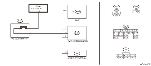
WIRING DIAGRAM:
1. Prepare the vehicle.
NOTE:
Check that the ambient temperature is 25 — 40°C (77 — 104°F) and that the humidity is 30% — 80%.
• Place the vehicle in the workshop or in the shade and windless condition.
• Open all windows.
2. Set the vehicle to the following conditions and idle the engine for 15 minutes.
Item | Condition |
Engine | Idling |
Air vent grille | Shutter is fully open. |
A/C switch | OFF |
Temperature adjustment dial | LO (MAX COOL) |
FRESH/RECIRC switch | RECIRC |
Air flow control dial | VENT |
Fan dial | 3/4 level |
3. Check evaporator sensor power supply input
Preparation tool:
Circuit tester
(1) Turn the ignition switch to OFF.
(2) Disconnect the evaporator sensor connector.
(3) Turn the ignition switch to ON.
(4) Measure the voltage between evaporator sensor connector and chassis ground.
Connector & terminal
(B88) No. 3 (+) — Chassis ground (−):
(5) Is the voltage approx. 12 V?
• Yes > Go to step 4).
• No > Repair or replace the harness.
4. Check evaporator sensor ground circuit
(1) Turn the ignition switch to OFF.
(2) Check continuity between evaporator sensor connector and chassis ground.
Connector & terminal
(B88) No. 2 — Chassis ground:
(3) Is there continuity?
• Yes > Go to step 6).
• No > Go to step 5).
5. Check open circuit in evaporator sensor ground circuit
(1) Disconnect the control panel connector.
(2) Check continuity between evaporator sensor connector and control panel connector.
Connector & terminal
(B88) No. 2 — (i16) No. 2:
(3) Is there continuity?
• Yes > Replace the control panel.
• No > Repair or replace the harness.
6. Check evaporator sensor signal output
(1) Connect the evaporator sensor connector and the control panel connector.
(2) Disconnect the engine control module (ECM) connector.
(3) Turn the ignition switch to ON.
(4) Turn the A/C switch to ON.
(5) Measure the voltage between engine control module (ECM) connector and chassis ground.
Connector & terminal
(B137) No. 26 (+) — Chassis ground (−):
(6) Is the voltage approx. 8 V or more?
• Yes > Evaporator sensor is normal.
• No > Go to step 7).
7. Check open circuit in evaporator sensor signal output circuit
(1) Turn the ignition switch to OFF.
(2) Disconnect the evaporator sensor connector.
(3) Check continuity between evaporator sensor connector and engine control module (ECM) connector.
Connector & terminal
(B88) No. 1 — (B137) No. 26:
(4) Is there continuity?
• Yes > Replace the evaporator sensor.
• No > Repair or replace the harness.
2. AUTO A/C MODEL
1. Prepare the vehicle.
NOTE:
Check that the ambient temperature is 25 — 40°C (77 — 104°F) and that the humidity is 30% — 80%.
• Place the vehicle in the workshop or in the shade and windless condition.
• Open all windows.
2. Set the vehicle to the following conditions.
Item | Condition |
Engine | Idling |
Air vent grille | Shutter is fully open. |
A/C switch | OFF |
Temperature adjustment dial | LO (MAX COOL) |
FRESH/RECIRC switch | RECIRC |
Air flow control dial or switch | VENT |
Fan dial | 5/7 level |
3. Using the Subaru Select Monitor, check «Evaporator Temperature».
NOTE:
For detailed operation procedures, refer to “Application help”.
(1) Idle the engine for 15 minutes, and then compare the air flow outlet temperature with «Evaporator Temperature».
Preparation tool:
Thermometer and hygrometer
NOTE:
For outlet opening temperature, measure the average temperature of center grille assembly and side grille assembly.
(2) Do the air flow outlet temperature and «Evaporator Temperature» differ by 3°C (5.4°F) or more?
• Yes > Go to step 4).
• No > Evaporator sensor is normal.
4. Check the evaporator sensor.
(1) Disconnect the evaporator sensor connector.
(2) Is the resistance between terminals of evaporator sensor within standard value?
Preparation tool:
Circuit tester
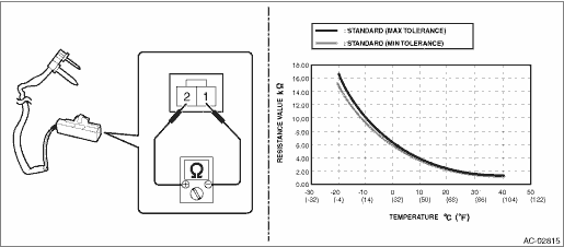
Terminal No. | Inspection conditions | Standard |
1 — 2 | −20°C | 15.37 — 16.62 k? |
−15°C | 12.09 — 12.87 k? | |
−10°C | 9.576 — 10.05 k? | |
−5°C | 7.636 — 7.899 k? | |
0°C | 6.132 — 6.256 k? | |
5°C | 4.891 — 5.057 k? | |
10°C | 3.928 — 4.113 k? | |
15°C | 3.174 — 3.366 k? | |
20°C | 2.581 — 2.77 k? | |
25°C | 2.111 — 2.292 k? | |
30°C | 1.737 — 1.907 k? | |
35°C | 1.437 — 1.595 k? | |
40°C | 1.195 — 1.34 k? |
• Yes > Evaporator sensor is normal.
• No > Replace the evaporator sensor.

 Removal
HVAC SYSTEM (HEATER, VENTILATOR AND A/C) > Evaporator SensorREMOVALCAUTION:Before handling the airbag system components, refer to “CAUTION” of “General Description” in &ldqu ...
Other materials:
Caution
BRAKE > General DescriptionCAUTION• Wear appropriate work clothing, including a helmet, protective goggles and protective shoes when performing any work.• Before removal, installation or disassembly, be sure to clarify the failure. Avoid unnecessary removal, installation, disassembly ...
Installation
FUEL INJECTION (FUEL SYSTEMS)(H4DO) > Fuel Delivery and Evaporation LinesINSTALLATIONInstall in the reverse order of removal while being careful of the following.NOTE:When connecting the fuel delivery tube (a) and evaporation hose (b), let the bushing (c) contact the quick connector (d) of fuel d ...
Specification
FUEL INJECTION (FUEL SYSTEMS)(H4DO) > General DescriptionSPECIFICATIONFuel tankCapacity60 L (15.9 US gal, 13.2 Imp gal)LocationUnder rear seatFuel pumpTypeImpellerShutoff discharge pressure750 kPa (7.7 kg/cm2, 108.8 psi) or lessDischarge rate82 L (21.7 US gal, 18 Imp gal)/h or more[12.5 V at 343 ...
