Subaru Crosstrek Service Manual: Inspection
DIFFERENTIALS > Rear Differential (VA-type)
INSPECTION
Wash all the disassembled parts clean, and examine them for wear, damage or other defects. Repair or replace the defective parts as necessary.
1. Hypoid driven gear and drive pinion
• If there is evidently an abnormal tooth contact, find out the cause and adjust until the teeth contact correctly. Replace the gear if there is an excessive worn or an incapable adjustment.
• If crack, cutout or seizure is found, replace the parts as a set. Slight damage of some teeth can be corrected by oil stone or the like.
2. Side gear and pinion mate gear
• Replace if cracks, scoring or other defects are evident on the tooth surface.
• Replace if thrust washer contact surface is worn or seized. Slight damages of the surface can be corrected by oil stones or equivalent.
3. Bearing
Replace if seizure, peeling, wear, rust, dragging during rotation, noise or other defect is evident.
4. Side gear thrust washer
Replace if seized, flawed, abnormally worn or having other defects.
5. Oil seal
Replace if deformed or damaged, and at every disassembling.
6. Differential carrier
Replace if the bearing bores are worn or damaged.
7. Differential case
Replace if its sliding surfaces are abnormally worn, burned, or cracked.
8. Companion flange
Replace if the oil seal lip contact surface shows cracking.
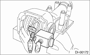
1. SIDE GEAR BACKLASH
Using a dial gauge, check the backlash of side gear.
Side gear backlash:
0.05 — 0.15 mm (0.002 — 0.006 in)
If the side gear backlash is outside the specification range, select the side gear thrust washer and adjust the side gear backlash as specified.
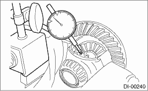
2. HYPOID DRIVEN GEAR BACKLASH
Using a dial gauge, check the backlash of hypoid driven gear.
Hypoid driven gear backlash:
0.10 — 0.15 mm (0.004 — 0.006 in)
If the hypoid driven gear backlash is outside the specification range, adjust the side bearing preload and repair if necessary.
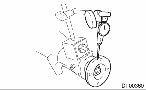
3. COMPANION FLANGE
1. If rust or dirt is attached to the companion flange, remove them.
2. Set a dial gauge at a companion flange surface (mating surface of propeller shaft and companion flange), and then measure the companion flange runout.
Limit of runout:
0.08 mm (0.003 in)
3. Set the gauge inside of the companion flange, and measure the runout.
Limit of runout:
0.08 mm (0.003 in)
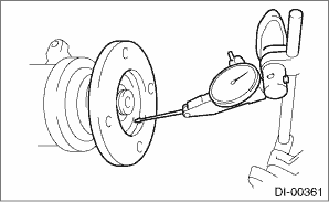
4. If either runout exceeds the limit, move the phase of companion flange and drive pinion 90° each, and find the point where the runout is within the limit.
5. If the runout exceeds the limit even after changing the phase, replace the companion flange and recheck the runout.
6. If the runout exceeds the limit after replacing the companion flange, the drive pinion may be assembled incorrectly or bearing is faulty.
4. TOOTH CONTACT BETWEEN HYPOID DRIVEN GEAR AND DRIVE PINION
Inspect the tooth contact between the hypoid driven gear and drive pinion. Rear Differential (VA-type) > ASSEMBLY">
 Disassembly
DIFFERENTIALS > Rear Differential (VA-type)DISASSEMBLYTo detect the real cause of trouble, inspect the following items before disassembling.• Tooth contact and backlash between hypoid driven ...
 Installation
DIFFERENTIALS > Rear Differential (VA-type)INSTALLATIONThe installation procedure for VA1-type is included in “INSTALLATION” for T-type. Rear Differential (T-type) > INSTALLATION&qu ...
Other materials:
Dtc b2a0c dcm internal fault
TELEMATICS SYSTEM (DIAGNOSTICS) > Diagnostic Procedure with Diagnostic Trouble Code (DTC)DTC B2A0C DCM INTERNAL FAULTDIAGNOSIS START CONDITION:When ignition switch is ON.DTC DETECTING CONDITION:• Main microcomputer and communication circuit IC cannot communicate. (Defective IPC)• SIM ...
Check list for interview Check
LAN SYSTEM (DIAGNOSTICS) > Check List for InterviewCHECKInspect the following item about the vehicle’s state.1. DISPLAY STATUS IN THE COMBINATION METERDisplay status in the combination meterEngine coolant temperature gauge display OK / NGFuel gauge display OK / NGTachometer display OK / ...
Installation
CONTINUOUSLY VARIABLE TRANSMISSION(TR580) > Reduction Drive GearINSTALLATION1. Install the reduction drive gear to secondary pulley.2. Select the reduction drive gear shim. Reduction Drive Gear > ADJUSTMENT">3. Install the dish plates, spring retainers, and selected reduction drive ge ...
