Subaru Crosstrek Service Manual: Inspection
CONTROL SYSTEMS > AT Shift Lock Control System
INSPECTION
1. SHIFT LOCK OPERATION
• Model without push button ignition switch
| STEP | CHECK | YES | NO |
1.CHECK COMMUNICATION OF SUBARU SELECT MONITOR.
1) Turn the ignition switch to ON.
2) Using the Subaru Select Monitor, check whether communication to all systems can be executed normally.
Is the system name displayed?
AT Shift Lock Control System > INSPECTION">Go to Step 2.
Perform the inspection following the diagnostic procedure in BODY CONTROL SYSTEM (DIAGNOSTICS) section. Basic Diagnostic Procedure">
2.CHECK SHIFT LOCK.
1) Turn the ignition switch to ON.
2) Shift the select lever to “P” range.
While brake pedal is not depressed, is it possible to move the select lever from the “P” range to other ranges?
Perform the inspection of “SELECT LEVER CANNOT BE LOCKED OR RELEASED”. AT Shift Lock Control System > INSPECTION">
AT Shift Lock Control System > INSPECTION">Go to Step 3.
3.CHECK SHIFT LOCK.
While brake pedal is depressed, is it possible to move the select lever from the “P” range to other ranges?
AT Shift Lock Control System > INSPECTION">Go to Step 4.
Perform the inspection of “SELECT LEVER CANNOT BE LOCKED OR RELEASED”. AT Shift Lock Control System > INSPECTION">
4.CHECK SHIFT LOCK.
Shift the select lever to “N” range.
Is it possible to move the select lever from the “N” range to the “P” range?
AT Shift Lock Control System > INSPECTION">Go to Step 5.
Perform the inspection of “SELECT LEVER CANNOT BE LOCKED OR RELEASED”. AT Shift Lock Control System > INSPECTION">
5.CHECK SHIFT LOCK.
1) Shift the select lever to “N” range.
2) Turn the ignition switch to ACC.
While brake pedal is depressed, is it possible to move the select lever from the “N” range to the “P” range?
AT Shift Lock Control System > INSPECTION">Go to Step 6.
Perform the inspection of “SELECT LEVER CANNOT BE LOCKED OR RELEASED”. AT Shift Lock Control System > INSPECTION">
6.CHECK KEY INTERLOCK.
1) Turn the ignition switch to OFF.
2) Shift the select lever to other than “P” range.
Can the ignition key be removed?
Perform the inspection of “KEY INTERLOCK CANNOT BE LOCKED OR RELEASED”. AT Shift Lock Control System > INSPECTION">
AT Shift Lock Control System > INSPECTION">Go to Step 7.
7.CHECK KEY INTERLOCK.
Shift the select lever to “P” range.
Can the ignition key be removed?
AT shift lock system is normal.
Perform the inspection of “KEY INTERLOCK CANNOT BE LOCKED OR RELEASED”. AT Shift Lock Control System > INSPECTION">
• Model with push button ignition switch
| STEP | CHECK | YES | NO |
1.CHECK COMMUNICATION OF SUBARU SELECT MONITOR.
1) Turn the ignition switch to ON.
2) Using the Subaru Select Monitor, check whether communication to all systems can be executed normally.
Is the system name displayed?
AT Shift Lock Control System > INSPECTION">Go to Step 2.
Perform the inspection following the diagnostic procedure in BODY CONTROL SYSTEM (DIAGNOSTICS) section. Basic Diagnostic Procedure">
2.CHECK SHIFT LOCK.
1) Turn the ignition switch to ON.
2) Shift the select lever to “P” range.
While brake pedal is not depressed, is it possible to move the select lever from the “P” range to other ranges?
Perform the inspection of “SELECT LEVER CANNOT BE LOCKED OR RELEASED”. AT Shift Lock Control System > INSPECTION">
AT Shift Lock Control System > INSPECTION">Go to Step 3.
3.CHECK SHIFT LOCK.
While brake pedal is depressed, is it possible to move the select lever from the “P” range to other ranges?
AT Shift Lock Control System > INSPECTION">Go to Step 4.
Perform the inspection of “SELECT LEVER CANNOT BE LOCKED OR RELEASED”. AT Shift Lock Control System > INSPECTION">
4.CHECK SHIFT LOCK.
Shift the select lever to “N” range.
Is it possible to move the select lever from the “N” range to the “P” range?
AT Shift Lock Control System > INSPECTION">Go to Step 5.
Perform the inspection of “SELECT LEVER CANNOT BE LOCKED OR RELEASED”. AT Shift Lock Control System > INSPECTION">
5.CHECK SHIFT LOCK.
1) Shift the select lever to “N” range.
2) Turn the ignition switch to ACC.
While brake pedal is depressed, is it possible to move the select lever from the “N” range to the “P” range?
AT shift lock system is normal.
Perform the inspection of “SELECT LEVER CANNOT BE LOCKED OR RELEASED”. AT Shift Lock Control System > INSPECTION">
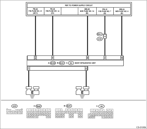
2. BODY INTEGRATED UNIT POWER SUPPLY AND GROUND CIRCUIT
NOTE:
For the DC power supply circuit, refer to “WIRING DIAGRAMS”. Power Supply Circuit">
| STEP | CHECK | YES | NO |
1.CHECK DTC OF BODY INTEGRATED UNIT.
Check DTC of body integrated unit.
Read Diagnostic Trouble Code (DTC)">
Is the DTC of power line displayed on body integrated unit?
Repair or replace it according to the DTC.
AT Shift Lock Control System > INSPECTION">Go to Step 2.
2.CHECK HARNESS BETWEEN BODY INTEGRATED UNIT AND BATTERY.
1) Turn the ignition switch to ON.
2) Measure the voltage between body integrated unit and chassis ground.
Connector & terminal
(B281) No. 3 (+) — Chassis ground (−):
(B280) No. 32 (+) — Chassis ground (−):
(B281) No. 6 (+) — Chassis ground (−):
(B281) No. 7 (+) — Chassis ground (−):
(i84) No. 6 (+) — Chassis ground (−):
Is the voltage 9 — 16 V?
AT Shift Lock Control System > INSPECTION">Go to Step 3.
Check harness for open circuit between the body integrated unit and the battery or a blown fuse.
3.CHECK HARNESS BETWEEN BODY INTEGRATED UNIT AND CHASSIS GROUND.
1) Turn the ignition switch to OFF.
2) Measure the harness resistance between the body integrated unit and chassis ground.
Connector & terminal
(B280) No. 1 — Chassis ground:
(i84) No. 1 — Chassis ground:
Is the resistance less than 1 ??
AT Shift Lock Control System > INSPECTION">Go to Step 4.
Repair the open circuit of harness between the body integrated unit and chassis ground.
4.CHECK FOR POOR CONTACT.
Is there poor contact of connector?
Repair the poor contact.
Check body integrated unit.
3. SELECT LEVER CANNOT BE LOCKED OR RELEASED
| STEP | CHECK | YES | NO |
1.CHECK BODY INTEGRATED UNIT POWER SUPPLY AND GROUND CIRCUIT.
AT Shift Lock Control System > INSPECTION">
Is there any fault?
Follow the procedures to perform inspection and repair.
AT Shift Lock Control System > INSPECTION">Go to Step 2.
2.CHECK CURRENT DATA.
1) Connect the Subaru Select Monitor.
2) Shift the select lever to “P” range.
3) Turn the ignition switch to ON.
4) Select the current data display and display «P SW». Read Current Data">
Is the display “ON” in the P range and “OFF” in ranges other than P?
AT Shift Lock Control System > INSPECTION">Go to Step 3.
AT Shift Lock Control System > INSPECTION">Go to Step 8.
3.CHECK CURRENT DATA.
Select the current data display and display «Stop Light Switch». Read Current Data">
Is “ON” displayed when the brake pedal is depressed and “OFF” displayed when the brake pedal is released?
AT Shift Lock Control System > INSPECTION">Go to Step 4.
AT Shift Lock Control System > INSPECTION">Go to Step 11.
4.CHECK BODY INTEGRATED UNIT DTC.
Check the DTC of the body integrated unit when the brake pedal is pressed and when it is released.
(Hold each condition for 5 seconds or more.)
Is there a DTC of a current malfunction?
Follow the DTC to perform inspection and repair.
AT Shift Lock Control System > INSPECTION">Go to Step 5.
5.CHECK CURRENT DATA.
Select the current data display and display «Shift lock solenoid output». Read Current Data">
Is “ON” displayed when the brake pedal is depressed and “OFF” displayed when the brake pedal is released?
AT Shift Lock Control System > INSPECTION">Go to Step 6.
Replace the body integrated unit.
6.CHECK CURRENT DATA.
Select the current data display and display «Shift Position». Read Current Data">
Is the display “P” in the P range and other than “P” in ranges other than P?
AT Shift Lock Control System > INSPECTION">Go to Step 7.
Check the following items.
• Inhibitor switch
• Harness between inhibitor switch and TCM
• TCM input signal
• TCM CAN communication
• Body integrated unit CAN receive
7.CHECK CURRENT DATA.
1) Select the current data display and display «Front Wheel Speed». Read Current Data">
2) Start the engine.
3) Raise vehicle speed gradually up to approximately 20 km/h (12 MPH).
Is a figure equivalent to the speedometer being indicated?
AT Shift Lock Control System > INSPECTION">Go to Step 12.
Check the following items.
• Wheel speed sensor
• CAN communication by VDC unit
• Body integrated unit CAN receive
Replace the wheel speed sensor, VDC unit or body integrated unit, or both.
8.CHECK HARNESS BETWEEN BODY INTEGRATED UNIT AND “P” RANGE SWITCH.
1) Disconnect the connector from body integrated unit.
2) Disconnect the connector of “P” range switch.
3) Check for open circuit of harness, short circuit to battery or short circuit to ground between the body integrated unit and “P” range switch.
Connector & terminal
(B281) No. 18 — (B116) No. 1:
Is there any fault in the harness?
Repair or replace the harness between the body integrated unit and the “P” range switch.
AT Shift Lock Control System > INSPECTION">Go to Step 9.
9.CHECK HARNESS BETWEEN “P” RANGE SWITCH AND CHASSIS GROUND.
Measure the resistance of harness between “P” range switch and chassis ground.
Connector & terminal
(B116) No. 2 — Chassis ground:
Is it less than 10 ??
AT Shift Lock Control System > INSPECTION">Go to Step 10.
Repair or replace the harness between the “P” range switch and chassis ground.
10.CHECK “P” RANGE SWITCH.
Measure the resistance between “P” range switch connector terminals.
Terminals
No. 2 — No. 1:
Is it less than 10 ? in the “P” range, and 1 M? or more in ranges other than “P”?
Replace the body integrated unit.
Replace the “P” range switch.
11.CHECK STOP LIGHT SWITCH INPUT SIGNAL.
1) Disconnect the connector from body integrated unit.
2) Measure the voltage between the body integrated unit connector terminal and chassis ground.
Connector & terminal
(B280) No. 10 (+) — Chassis ground (−):
Is the voltage 9 V to 16 V when the brake pedal is depressed, and approx. 0 V when not depressed?
Replace the body integrated unit.
Check the stop light system.
12.CHECK SOLENOID UNIT OPERATION.
Connect the battery to the solenoid unit connector terminal, and operate the solenoid unit.
Terminals
No. 3 (+) — No. 4 (−):
Does the solenoid unit operate normally?
Check the lock mechanism of the select lever body.
Replace the solenoid unit.
4. KEY INTERLOCK CANNOT BE LOCKED OR RELEASED
NOTE:
Check of this item only applies to models without a push button ignition switch.
| STEP | CHECK | YES | NO |
1.CHECK D CHECK FUSE.
Check that the D check fuse is disconnected.
Is the D check fuse disconnected?
AT Shift Lock Control System > INSPECTION">Go to Step 2.
Remove the D check fuse and then turn the ignition switch to ON.
2.CHECK BODY INTEGRATED UNIT POWER SUPPLY AND GROUND CIRCUIT.
AT Shift Lock Control System > INSPECTION">
Is there any fault?
Follow the procedures to inspect and repair.
AT Shift Lock Control System > INSPECTION">Go to Step 3.
3.CHECK CURRENT DATA.
1) Connect the Subaru Select Monitor.
2) Shift the select lever to “P” range.
3) Turn the ignition switch to ON.
4) Select the current data display and display «P SW». Read Current Data">
Is the display “ON” in the P range and “OFF” in ranges other than P?
AT Shift Lock Control System > INSPECTION">Go to Step 4.
AT Shift Lock Control System > INSPECTION">Go to Step 7.
4.CHECK CURRENT DATA.
1) Select the current data display and display the «key-lock warning SW». Read Current Data">
2) Turn the ignition switch to OFF.
Does the display change from “ON” ←> “OFF” when the key is inserted and removed?
AT Shift Lock Control System > INSPECTION">Go to Step 5.
AT Shift Lock Control System > INSPECTION">Go to Step 10.
5.CHECK CURRENT DATA.
1) Turn the ignition switch to ON.
2) Select the current data display and display «Key lock solenoid output». Read Current Data">
Is the display “OFF” in the P range and “ON” in ranges other than P?
AT Shift Lock Control System > INSPECTION">Go to Step 11.
AT Shift Lock Control System > INSPECTION">Go to Step 6.
6.CHECK DTC OF BODY INTEGRATED UNIT.
1) Set the select lever to other than “P” range.
2) Check DTC of body integrated unit.
Is B1015 (key interlock circuit abnormal) a current malfunction?
Follow the DTC to perform inspection and repair.
AT Shift Lock Control System > INSPECTION">Go to Step 11.
7.CHECK HARNESS BETWEEN BODY INTEGRATED UNIT AND “P” RANGE SWITCH.
1) Disconnect the connector from body integrated unit.
2) Disconnect the connector of “P” range switch.
3) Check for open circuit of harness, short circuit to battery or short circuit to ground between the body integrated unit and “P” range switch.
Connector & terminal
(B281) No. 18 — (B116) No. 1:
Is there any fault in the harness?
Repair or replace the harness between the body integrated unit and the “P” range switch.
AT Shift Lock Control System > INSPECTION">Go to Step 8.
8.CHECK HARNESS BETWEEN “P” RANGE SWITCH AND CHASSIS GROUND.
Measure the resistance of harness between “P” range switch and chassis ground.
Connector & terminal
(B116) No. 2 — Chassis ground:
Is it less than 10 ??
AT Shift Lock Control System > INSPECTION">Go to Step 9.
Repair or replace the harness between the “P” range switch and chassis ground.
9.CHECK “P” RANGE SWITCH.
Measure the resistance between “P” range switch connector terminals.
Terminals
 Electrical specification
CONTROL SYSTEMS > AT Shift Lock Control SystemELECTRICAL SPECIFICATION• Model without push button ignition switchItemConnector No.Terminal No.Input/Output signalMeasured value and measuring c ...
 Location
CONTROL SYSTEMS > AT Shift Lock Control SystemLOCATION1. MODEL WITHOUT PUSH BUTTON IGNITION SWITCH(1)TCM (“P” range)(4)Key cylinder (with built-in key warning switch)(6)“P” ...
Other materials:
Inspection
ENTERTAINMENT > Audio SystemINSPECTION1. BASIC INSPECTIONModel with 6.2 inch display1. Using the Check List for Interview, ask the customer the condition of how the trouble occurred. Check List for Interview > CHECK">2. Check the battery. Battery > INSPECTION">3. Check the ...
Dtc p0977 shift solenoid "b" control circuit high
CONTINUOUSLY VARIABLE TRANSMISSION (DIAGNOSTICS) > Diagnostic Procedure with Diagnostic Trouble Code (DTC)DTC P0977 SHIFT SOLENOID "B" CONTROL CIRCUIT HIGHDTC detecting condition:Immediately at fault recognitionTrouble symptom:Gear is not changed. (No down-shift)CAUTION:Use the check bo ...
Dtc c0027 rear left abs sensor circuit open or short
VEHICLE DYNAMICS CONTROL (VDC) (DIAGNOSTICS) > Diagnostic Procedure with Diagnostic Trouble Code (DTC)DTC C0027 REAR LEFT ABS SENSOR CIRCUIT OPEN OR SHORTDTC detecting condition:• Defective ABS wheel speed sensor (broken wire, input voltage too high)• Defective harness connectorTroubl ...
