Subaru Crosstrek Service Manual: Inspection
CLUTCH SYSTEM > Clutch Switch
INSPECTION
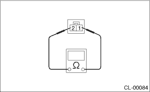
1. CLUTCH START SWITCH
1. Perform the following inspections. If the clutch start switch does not operate normally, adjust the switch, and check it again. Clutch Switch > ADJUSTMENT">
• Make sure that engine does not start with clutch pedal not depressed.
• Make sure that engine starts with clutch pedal fully depressed.
2. When the clutch start switch does not operate normally even if it is adjusted, check the clutch start switch for continuity.
(1) Remove the clutch start switch. Clutch Switch > REMOVAL">
(2) Measure the resistance between terminal 1 and 2 of the switch. If the resistance is not at the standard value, replace the switch.
Condition | Terminal No. | Specified resistance |
ON | No. 1 — No. 2 | Less than 1 ? |
OFF | No. 1 — No. 2 | 1 M? or more |
(3) Check that the switch is turned on and off in dimension L.
Dimension L:
9 — 10 mm (0.35 — 0.39 in)
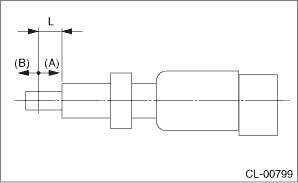
(A) | ON |
(B) | OFF |
(4) Install the clutch start switch. Clutch Switch > INSTALLATION">
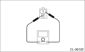
2. CLUTCH SWITCH
1. Check the clutch switch for continuity.
(1) Disconnect the connector of clutch switch.
(2) Measure the resistance between terminal 1 and 2 of the switch. If the resistance is not within the specification, check the clutch stroke and installation condition, and check the clutch switch again.
Condition | Terminal No. | Specified resistance |
When clutch pedal is depressed | No. 1 — No. 2 | 1 M? or more |
When the clutch pedal is not depressed | No. 1 — No. 2 | Less than 1 ? |
2. When the clutch switch does not operate normally even if the clutch stroke and installation condition are normal, check the clutch switch for continuity.
(1) Remove the clutch switches. Clutch Switch > REMOVAL">
(2) Measure the resistance between terminal 1 and 2 of the switch. If the resistance is not at the standard value, replace the switch.
Condition | Terminal No. | Specified resistance |
ON | No. 1 — No. 2 | Less than 1 ? |
OFF | No. 1 — No. 2 | 1 M? or more |
(3) Check that the switch is turned on and off in dimension L.
Dimension L:
5 — 6.5 mm (0.2 — 0.26 in)
(A) | ON |
(B) | OFF |
(4) Install the clutch switch. Clutch Switch > INSTALLATION">
 Removal
CLUTCH SYSTEM > Clutch SwitchREMOVALCAUTION:Before handling the airbag system components, refer to “CAUTION” of “General Description” in “AIRBAG SYSTEM”. Genera ...
 Installation
CLUTCH SYSTEM > Clutch SwitchINSTALLATION1. CLUTCH SWITCH1. Install the clutch switch.2. Move the clevis pin of push rod to left and right, retain it at the position where it moves smoothly, and me ...
Other materials:
Drive cycle Procedure
ENGINE (DIAGNOSTICS)(H4DO) > Drive CyclePROCEDUREIt is necessary to perform the drive cycle listed below if DTC is not found in the Inspection Mode. It is possible to complete diagnosis of the DTC by performing the indicated drive cycle. After the repair for the DTC, perform a necessary drive cyc ...
Inspection
GLASS/WINDOWS/MIRRORS > Rear Window Defogger SystemINSPECTION1. CHECK SYSTEMSymptomsInspection orderRear window defogger does not operate.(1) Check the fuse.(2) Check the rear defogger relay.(3) Check the rear window defogger switch.(4) Check the heat wire.(5) Check the wiring harness.(6) Check b ...
SRS side airbag and SRS curtain airbag
The SRS side airbag is stored in the door
side of each front seat seatback, which
bears an "SRS AIRBAG" label.
In a moderate to severe side impact
collision, the SRS side airbag on the
impacted side of the vehicle deploys
between the occupant and the door panel
and supplements the seatbel ...
