Subaru Crosstrek Service Manual: Inspection
CLUTCH SYSTEM > Clutch Disc and Cover
INSPECTION
1. CLUTCH DISC
1. Facing wear
Measure the depth from the facing surface to the rivet head. Replace if the face is worn locally or worn down to less than the specified value.
Depth to rivet head:
Limit of sinking
0.8 mm (0.031 in)
NOTE:
Do not wash the clutch disc with any type of cleaning fluid.
2. Hardened facing
Replace the clutch disc.
3. Oil soakage on facing
Replace the clutch disc and inspect the transmission front oil seal, transmission case mating surface, engine rear oil seal and other locations for oil leakage.

(A) | Clutch facing |
4. Deflection on facing
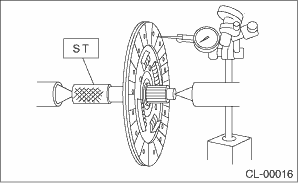
If deflection exceeds the specified value at the outer circumference of the facing, replace the clutch disc.
| ST 499747100 | CLUTCH DISC GUIDE |
Limit for deflection:
0.7 mm (0.028 in) at R = 110 mm (4.33 in)
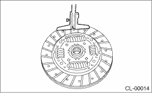
5. If there is spline wear, loose rivets, failed damper springs, etc., replace the clutch disc.
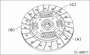
(A) | Spline |
(B) | Rivet |
(C) | Damper spring |
2. CLUTCH COVER
NOTE:
Visually check the following items without disassembling, and replace or repair if defective.
1. Loose thrust rivet
2. Damaged or worn bearing contact area at the center of diaphragm spring
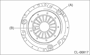
(A) | Thrust rivet |
(B) | Diaphragm spring |
3. Damaged or worn disc contact surface of the pressure plate
4. Loose strap plate installation area
5. Worn diaphragm sliding area
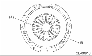
(A) | Pressure plate |
(B) | Strap plate |

 Removal
CLUTCH SYSTEM > Clutch Disc and CoverREMOVAL1. Remove the transmission assembly from the vehicle. Manual Transmission Assembly > REMOVAL">2. Attach the ST on the flywheel.ST 499747100 ...
Other materials:
Operation
INSTRUMENTATION/DRIVER INFO (DIAGNOSTICS) > Read Current DataOPERATION1. COMBINATION METER1. On «Start» display, select «Diagnosis».2. On «Vehicle selection» display, input the target vehicle information and select «Confirmed».3. On «Main Menu» display, select «Each System».4. On «Se ...
Continuously variable transmission features
The continuously variable transmission (CVT) in the Subaru Ascent is an advanced
electronically managed system designed to deliver seamless acceleration, optimal
efficiency, and smooth driving dynamics. Unlike traditional gearboxes, it offers
an infinite range of forward gear ratios along with ...
Diagnostics with phenomenon Inspection
CONTINUOUSLY VARIABLE TRANSMISSION(TR580) > Diagnostics with PhenomenonINSPECTIONSymptomsFaulty partsStall speed is low after warming-up, with select lever in “D” or “R” range.Engine control systemVehicle does not move despite engine speed rising up, with select lever in & ...
