
Subaru Crosstrek Service Manual: Inspection
BRAKE > Stop Light Switch
INSPECTION
1. CLEARANCE CHECK
NOTE:
Check for clearance is applied only to LED model.
1. Measure the clearance between the end of the stop light switch and the stopper.
Specification:
Clearance (A) of the stop light switch: 1 mm — 2 mm (0.04 in — 0.08 in)
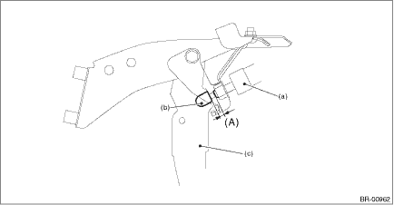
(a) | Stop light switch | (b) | Stopper | (c) | Brake pedal |
2. Adjust the position of the stop light switch if the inspection result is not within the standard value. Stop Light Switch > ADJUSTMENT">
2. CHECK RESISTANCE
1. Disconnect the stop light switch connector.
2. Measure the resistance between stop light switch terminals.
Preparation tool:
Circuit tester
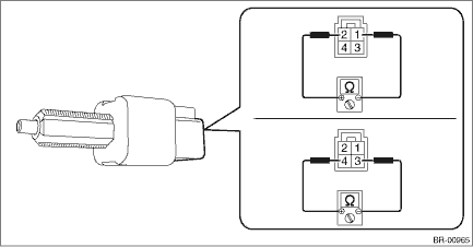
• Bulb type
Terminal No. | Inspection conditions | Standard |
1 — 2 | When brake pedal is depressed | 1 M? or more |
When brake pedal is released | Less than 1 ? | |
3 — 4 | When brake pedal is depressed | Less than 1 ? |
When brake pedal is released | 1 M? or more |
• LED type
Terminal No. | Inspection conditions | Standard |
1 — 2 | When brake pedal is depressed | Less than 1 ? |
When brake pedal is released | 1 M? or more | |
3 — 4 | When brake pedal is depressed | 1 M? or more |
When brake pedal is released | Less than 1 ? |
3. Replace the stop light switch if the inspection result is not within the standard value.
 Removal
BRAKE > Stop Light SwitchREMOVALCAUTION:Before handling the airbag system components, always refer to “CAUTION” of “General Description” in “AIRBAG SYSTEM”. Gen ...
 Installation
BRAKE > Stop Light SwitchINSTALLATION1. BULB TYPE1. Install the stop light switch.CAUTION:• Turn the stop light switch clockwise when installing so that it can return backward by approximatel ...
Other materials:
Assembly
CONTINUOUSLY VARIABLE TRANSMISSION(TR580) > Transmission CaseASSEMBLY1. Face the O-ring side of the CVTF filter to the transmission case side, and install the CVTF filter.NOTE:Apply CVTF to the O-ring of CVTF filter.2. Install the CVTF filter cover and gasket.NOTE:Use a new gasket.Tightening torq ...
Dtc u0416 invalid data received from vehicle dynamics control module
HVAC SYSTEM (AUTO A/C) (DIAGNOSTICS) > Diagnostic Procedure with Diagnostic Trouble Code (DTC)DTC U0416 INVALID DATA RECEIVED FROM VEHICLE DYNAMICS CONTROL MODULEThis is detected when CAN data from VDC is abnormal.NOTE:Perform the diagnosis for LAN system. Basic Diagnostic Procedure > PROCEDU ...
Dtc p0021 "a" camshaft position - timing over-advanced or system performance bank 2
ENGINE (DIAGNOSTICS)(H4DO) > Diagnostic Procedure with Diagnostic Trouble Code (DTC)DTC P0021 "A" CAMSHAFT POSITION - TIMING OVER-ADVANCED OR SYSTEM PERFORMANCE BANK 2DTC detecting condition:Detected when two consecutive driving cycles with fault occur.Trouble symptom:• Engine sta ...
