Subaru Crosstrek Owners Manual: Help line
The help line (distance marker and vehicle width line) is a guide to help you realize the actual distance from the screen image.
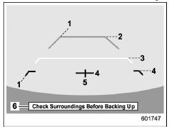
1) Vehicle width line (oblique vertical line)
2) Approx. 10 feet (3 m) from the bumper (green horizontal line)
3) Approx. 3 feet (1 m) from the bumper (yellow horizontal line)
4) Approx. 1.5 feet (0.5 m) from the bumper (red horizontal line)
5) Vehicle centerline
6) Warning message
When the shift lever/select lever is set to position "R", the monitor screen displays the help lines together with the rear view image.
CAUTION
- When moving backward, always check the back with your eyes without relying on the help lines.
- The actual position may be different from the indication of the help lines.
- Differences may occur due to number of passengers or loaded cargo.
- When the vehicle is on a slope or when the vehicle is inclined against the road, the indication is different from the actual position.
- Be sure to observe the displayed warning message.
NOTE
If you shift to the "R" range shortly after turning on the ignition switch, the warning message "Check Surroundings Before Backing Up" may not be displayed. Wait for several seconds or more after turning on the ignition switch before shifting to the "R" range.
Then the warning message will be displayed.
Difference between screen image and actual road
The distance markers show the distance for a level road when the vehicle is not loaded. It may be different from the actual distance depending on the loading conditions or road conditions.
When there is an upward slope at the back
- 3 feet (1 m)
The distance on the screen looks farther than the actual distance.
When there is a downward slope at the back
- 3 feet (1 m)
The distance on the screen looks nearer than the actual distance.
NOTE
When cargo is loaded, the rear view distance on the screen looks farther than the actual distance as in an upward slope.
Feature of distance marker
- 3 feet (1 m) line
- 10 feet (3 m) line
The distance marker shows the distance on the road. If there is a car or other object close behind, distance cannot be correctly displayed.
 Viewing range on the screen
CAUTION
The range that can be viewed with
the rear view camera is limited.
Always be sure to check with your
eyes when moving backward and
proceed slowly.
Range of view
Range of view
...

Other materials:
ECO gauge screen (if equipped)
Average fuel consumption corresponding
to the driving distance of each trip meter
ECO gauge
The gauge pointer shows the difference
between the current fuel consumption and
the average fuel consumption that is
displayed on the center part of the screen.
If the gauge pointer moves ...
Specification
CONTINUOUSLY VARIABLE TRANSMISSION(TR580) > General DescriptionSPECIFICATION1. TORQUE CONVERTERModelDOHC non-turboTypeSymmetric, 3-element, single stage, 2-phase torque converterStall torque ratio2.62Nominalmm (in)236 (9.29)Stall speed (at sea level)r/min2,150 — 2,800 (D range)1,950 — 2,550 ( ...
Inspection
EMISSION CONTROL (AUX. EMISSION CONTROL DEVICES)(H4DO) > EGR Control ValveINSPECTION1. Check that the EGR control valve has no deformation, cracks or other damages.2. Measure the resistance between EGR control valve terminals.Terminal No.Standard2 and 122±2 ?2 and 322±2 ?5 and 422±2 ?5 and 622 ...
