Subaru Crosstrek Service Manual: Fuel injector circuit
ENGINE (DIAGNOSTICS)(H4DO) > Diagnostics for Engine Starting Failure
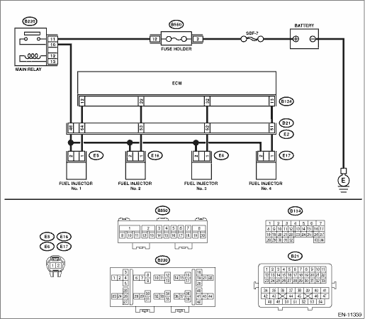
FUEL INJECTOR CIRCUIT
CAUTION:
• Check or repair only faulty parts.
• After servicing or replacing faulty parts, perform Clear Memory Mode Clear Memory Mode > OPERATION"> , and Inspection Mode Inspection Mode > PROCEDURE">.
WIRING DIAGRAM:
Engine electrical system Engine Electrical System">
| STEP | CHECK | YES | NO |
1.CHECK OPERATION OF EACH FUEL INJECTOR.
While cranking the engine, check each fuel injector emits operating sound. Use a sound scope or attach a screwdriver to the injector to listen to sounds for this check.
Does the fuel injector emit operating sound?
Check the fuel pressure. Fuel Pressure > INSPECTION">
Diagnostics for Engine Starting Failure > FUEL INJECTOR CIRCUIT">Go to Step 2.
2.CHECK POWER SUPPLY TO EACH FUEL INJECTOR.
1) Turn the ignition switch to OFF.
2) Disconnect the connector from fuel injector.
3) Turn the ignition switch to ON.
4) Measure the power supply voltage between fuel injector terminal and engine ground.
Connector & terminal
#1 (E5) No. 2 (+) — Engine ground (−):
#2 (E16) No. 2 (+) — Engine ground (−):
#3 (E6) No. 2 (+) — Engine ground (−):
#4 (E17) No. 2 (+) — Engine ground (−):
Is the voltage 10 V or more?
Diagnostics for Engine Starting Failure > FUEL INJECTOR CIRCUIT">Go to Step 3.
Repair the harness and connector.
NOTE:
In this case, repair the following item:
• Open circuit in harness between main relay connector and fuel injector connector
• Poor contact of main relay connector
• Poor contact of coupling connector
3.CHECK HARNESS BETWEEN ECM AND FUEL INJECTOR CONNECTOR.
1) Turn the ignition switch to OFF.
2) Disconnect the connector from ECM.
3) Measure the resistance of harness between ECM connector and fuel injector connector.
Connector & terminal
#1 (B134) No. 12 — (E5) No. 1:
#2 (B134) No. 22 — (E16) No. 1:
#3 (B134) No. 32 — (E6) No. 1:
#4 (B134) No. 13 — (E17) No. 1:
Is the resistance less than 1 ??
Diagnostics for Engine Starting Failure > FUEL INJECTOR CIRCUIT">Go to Step 4.
Repair the harness and connector.
NOTE:
In this case, repair the following item:
• Open circuit in harness between ECM connector and fuel injector connector
• Poor contact of coupling connector
4.CHECK HARNESS BETWEEN ECM AND FUEL INJECTOR CONNECTOR.
Measure the resistance between ECM connector and chassis ground.
Connector & terminal
#1 (B134) No. 12 — Chassis ground:
#2 (B134) No. 22 — Chassis ground:
#3 (B134) No. 32 — Chassis ground:
#4 (B134) No. 13 — Chassis ground:
Is the resistance 1 M? or more?
Diagnostics for Engine Starting Failure > FUEL INJECTOR CIRCUIT">Go to Step 5.
Repair the short circuit to ground in harness between ECM connector and fuel injector connector.
5.CHECK EACH FUEL INJECTOR.
Measure the resistance between each fuel injector terminals.
Terminals
No. 1 — No. 2:
Is the resistance 5 — 20 ??
Diagnostics for Engine Starting Failure > FUEL INJECTOR CIRCUIT">Go to Step 6.
Replace the faulty fuel injector. Fuel Injector">
6.CHECK FOR POOR CONTACT.
Check for poor contact of ECM connector.
Is there poor contact of ECM connector?
Repair the poor contact of ECM connector.
Inspection using “General Diagnostic Table” General Diagnostic Table > INSPECTION">
 Fuel pump circuit
ENGINE (DIAGNOSTICS)(H4DO) > Diagnostics for Engine Starting FailureFUEL PUMP CIRCUITCAUTION:After servicing or replacing faulty parts, perform Clear Memory Mode Clear Memory Mode > OPERATION&q ...

Other materials:
Dtc b2a01 tel1 antenna circuit
TELEMATICS SYSTEM (DIAGNOSTICS) > Diagnostic Procedure with Diagnostic Trouble Code (DTC)DTC B2A01 TEL1 ANTENNA CIRCUITDiagnosis start condition:When ignition switch is ON.DTC detecting condition:Any of the followings continues for 5 seconds or more.• TEL1 impedance is more than 1 M?. (Deta ...
Removal
SECURITY AND LOCKS > Keyless Access Indoor AntennaREMOVAL1. FRONT ANTENNA1. Disconnect the ground cable from battery. NOTE">2. Remove the cover - shift lever. Console Box > REMOVAL">3. Disconnect the connector and remove the front antenna assembly - interior.2. REAR ANTENNA1. ...
Certification
Bluetooth
The Bluetooth word mark and logo are
registered trademarks of Bluetooth SIG,
Inc. and any use of such marks by Clarion
Co., Ltd. is under license.
SiriusXM Satel l i t e Radio ( i f
equipped)
SiriusXMTM and all related marks and
logos are trademarks of SiriusXM Radio
Inc. All ri ...
