Subaru Crosstrek Service Manual: Electrical specification
AIRBAG SYSTEM (DIAGNOSTICS) > Airbag Control Module I/O Signal
ELECTRICAL SPECIFICATION
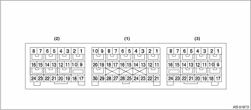
• Terminal numbers in airbag control module connector are shown in the figure.
• The airbag warning light illuminates when the connector is removed from the airbag control module.
Item | Control module terminal No. | ||
Ignition power supply | Dedicated fuse | (1) — 21 | |
Passenger’s airbag module level one | + | (1) — 4 | |
− | (1) — 3 | ||
Passenger’s airbag module level two | + | (1) — 1 | |
− | (1) — 2 | ||
Driver’s airbag module level one | + | (1) — 5 | |
− | (1) — 6 | ||
Driver’s airbag module level two | + | (1) — 8 | |
− | (1) — 7 | ||
Driver’s knee airbag module | + | (1) — 9 | |
− | (1) — 10 | ||
CAN-H | (1) — 13 | ||
CAN-L | (1) — 22 | ||
Collision detection signal | (1) — 24 | ||
Front sub sensor LH | + | (1) — 30 | |
− | (1) — 28 | ||
Front sub sensor RH | + | (1) — 29 | |
− | (1) — 27 | ||
Ground line (GND) | (1) — 25 | ||
(1) — 26 | |||
Passenger’s airbag ON indicator | (1) — 23 | ||
Passenger’s airbag OFF indicator | (1) — 17 | ||
Passenger’s seat belt warning | (1) — 15 | ||
Side airbag sensor LH Curtain airbag sensor LH Front door impact sensor LH | + | (2) — 24 | |
− | (2) — 23 | ||
Seat belt pretensioner LH | + | (2) — 5 | |
− | (2) — 6 | ||
Side airbag module LH | + | (2) — 1 | |
− | (2) — 2 | ||
Curtain airbag module LH | + | (2) — 4 | |
− | (2) — 3 | ||
Occupant detection control module | + | (3) — 16 | |
− | (3) — 24 | ||
Side airbag sensor RH Curtain airbag sensor RH Front door impact sensor RH | + | (3) — 17 | |
− | (3) — 18 | ||
Side airbag module RH | + | (3) — 8 | |
− | (3) — 7 | ||
Curtain airbag module RH | + | (3) — 5 | |
− | (3) — 6 | ||
Seat belt pretensioner RH | + | (3) — 4 | |
− | (3) — 3 | ||
Lap seat belt pretensioner RH | + | (3) — 1 | |
− | (3) — 2 | ||
Satellite safing sensor | + | (3) — 21 | |
− | (3) — 22 | ||

 Wiring diagram
AIRBAG SYSTEM (DIAGNOSTICS) > Airbag Control Module I/O SignalWIRING DIAGRAMRefer to “Airbag System” in WI section. Airbag System > WIRING DIAGRAM"> ...
Other materials:
Selecting a station from the list (if equipped)
A station list can be displayed.
1. Touch the tab.
2. Touch the tab and the station
list will
appear.
3. Select the desired station.
Update the station list
Touch the "Update Station List" key on the
station list screen and the following screen
will be displayed.
...
Tire pressure monitoring system (TPMS) (U.S.-spec. models)
Low tire pressure warning light (type A)
Low tire pressure warning light (type B)
The tire pressure monitoring system provides
the driver with a warning message
when tire pressure is severely low.
The tire pressure monitoring system will
activate only when the vehicle is driven at
s ...
Dtc u0100 lost communication with ecm/pcm a
CONTINUOUSLY VARIABLE TRANSMISSION (DIAGNOSTICS) > Diagnostic Procedure with Diagnostic Trouble Code (DTC)DTC U0100 LOST COMMUNICATION WITH ECM/PCM “A”NOTE:Refer to “LAN SYSTEM (DIAGNOSTICS)” for diagnostic procedures. Basic Diagnostic Procedure">1. OUTLINE OF DIA ...
