Subaru Crosstrek Service Manual: Electrical specification
POWER ASSISTED SYSTEM (POWER STEERING) (DIAGNOSTICS) > Control Module I/O Signal
ELECTRICAL SPECIFICATION
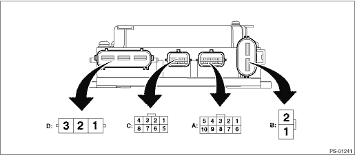
NOTE:
The terminal numbers of the power steering control module connectors are as indicated in the figure.
Contents | Terminal No. | Input/output signal |
Measured value and measuring conditions | ||
Power supply (IG SW) | A1 | Battery voltage is detected with the ignition switch ON when measuring between A1 — B1. |
Subaru Select Monitor communication line | A2 | Digital signal; can not be measured |
Shield GND | A3 | 0 V is constantly detected. |
Main torque sensor | A4 | The voltage changes when the steering is operated to the right or left with the ignition switch ON. |
Sub torque sensor | A5 | The voltage changes when the steering is operated to the right or left with the ignition switch ON. |
CAN communication | A6 | Digital signal; can not be measured |
CAN communication | A7 | Digital signal; can not be measured |
Torque sensor operating power supply | A8 | Approximately 8 V is detected with ignition switch ON. |
Torque sensor ground | A9 | 0 V is constantly detected. |
Torque sensor standard power supply | A10 | Approximately 3 V is detected with ignition switch ON. |
Ground | B1 | Battery voltage is constantly detected when measuring between B1 — B2. |
Power supply | B2 | |
Resolver S1 | C1 | Varies depending on the operational status of the motor. |
Resolver S3 | C2 | |
Resolver S2 | C3 | |
Resolver S4 | C4 | |
Excitation power supply for resolver | C5 | |
Common output | C6 | |
Motor U phase | D1 | Varies depending on the motor output. |
Motor V phase | D2 | |
Motor W phase | D3 |

 Wiring diagram
POWER ASSISTED SYSTEM (POWER STEERING) (DIAGNOSTICS) > Control Module I/O SignalWIRING DIAGRAM(1)Battery(5)Engine control module (ECM)(9)Torque sensor (main & sub)(2)Ignition switch(6)Power ste ...
Other materials:
Replacement
VEHICLE DYNAMICS CONTROL (VDC) > VDC Control Module and Hydraulic Control Unit (VDCCM&H/U)REPLACEMENT1. ONLY FOR MODELS WITHOUT EyeSightCAUTION:• Because the pressure sensor built into the H/U is easily damaged by static electricity, start the operation after performing static electrici ...
Installation
CLUTCH SYSTEM > Release Bearing and LeverINSTALLATIONNOTE:Apply the specified grease to lubricate to the following points before installation.• Contact surface of lever and pivot• Contact surface of lever and bearing• Transmission main shaft spline• Contact surface of rele ...
Removal
DIFFERENTIALS > Rear Differential (T-type)REMOVAL1. Shift the select lever or gear shift lever to neutral.2. Release the parking brake.3. Disconnect the ground cable from battery.4. Lift up the vehicle.5. Remove the rear wheels.6. Drain differential gear oil. Differential Gear Oil > REPLACEME ...
