Subaru Crosstrek Service Manual: Electrical specification
HVAC SYSTEM (AUTO A/C) (DIAGNOSTICS) > Auto A/C Control Module I/O Signal
ELECTRICAL SPECIFICATION
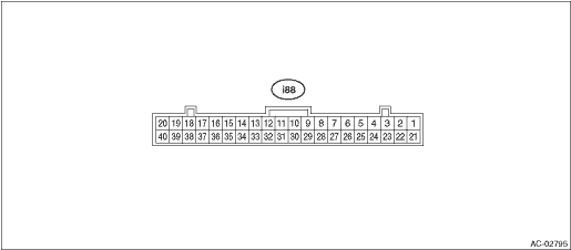
Terminal No. | Content | Measuring condition | Standard | |
1 | Mode door actuator #4 | Digital signal; can not be measured | — | |
2 | Mode door actuator #3 | Digital signal; can not be measured | — | |
3 | Mode door actuator #2 | Digital signal; can not be measured | — | |
4 | Mode door actuator #1 | Digital signal; can not be measured | — | |
6 | Intake door actuator (FRESH) | FRESH mode | 8 V or more | |
8 | Intake door actuator (RECIRC) | RECIRC mode | 8 V or more | |
9 | Blower fan ON signal | Blower fan is ON | 1 V or less | |
10 | Intake door potentiometer power supply | Ignition switch ON | 5 V | |
11 | A/C cut-off signal | A/C is cut off | 1 V or less | |
12 | Intake door potentiometer signal | Ignition switch ON | 0 — 5 V | |
14 | GND for sensors | Always | 1 V or less | |
15 | ACC power supply | ACC ON | Battery voltage | |
16 | Sunload sensor | Sunlight is contacting sensor | 1 — 4 V | |
17 | RECIRC sensor | Ignition switch ON | 25°C: 2.5 V | |
18 | Post evaporator sensor | Depends on temperature after the evaporator. | 1 — 4.5 V | |
19 | CAN Lo | Digital signal; can not be measured | — | |
20 | CAN Hi | Digital signal; can not be measured | — | |
21 | Air mix door actuator LH #4*2 | Digital signal; can not be measured | — | |
22 | Air mix door actuator LH #3*2 | Digital signal; can not be measured | — | |
23 | Air mix door actuator LH #2*2 | Digital signal; can not be measured | — | |
24 | Air mix door actuator LH #1*2 | Digital signal; can not be measured | — | |
25 | Air mix door actuator #4 *1 or air mix door actuator RH #4 *2 | Digital signal; can not be measured | — | |
26 | Air mix door actuator #3 *1 or air mix door actuator RH #3 *2 | Digital signal; can not be measured | — | |
27 | Air mix door actuator #2 *1 or air mix door actuator RH #2 *2 | Digital signal; can not be measured | — | |
28 | Air mix door actuator #1 *1 or air mix door actuator RH #1f *2 | Digital signal; can not be measured | — | |
31 | BATT | Always | Battery voltage | |
32 | IGN | Ignition ON | Battery voltage | |
34 | GND | Always | 1 V or less | |
35 | ILL− | Illumination ON (measure between 37 — 35) | Battery voltage | |
37 | ILL+ | |||
40 | Fan control signal | Ignition switch: ON, Blower switch: ON | 1st | Approx. 9 V |
2nd | Approx. 8 V | |||
3rd | Approx. 7 V | |||
4th | Approx. 6 V | |||
5th | Approx. 5 V | |||
6th | Approx. 3.5 V | |||
7th | Approx. 0.5 V | |||
*1: Without left/right independent air conditioning function
*2: With left/right independent air conditioning function

 Wiring diagram
HVAC SYSTEM (AUTO A/C) (DIAGNOSTICS) > Auto A/C Control Module I/O SignalWIRING DIAGRAM1. AIR CONDITIONER AUTO A/C MODELRefer to “Air Conditioning System” in the wiring diagram. Air Co ...
Other materials:
Removal
MANUAL TRANSMISSION AND DIFFERENTIAL(5MT) > Shifter Fork and RodREMOVAL1. Remove the manual transmission assembly from the vehicle. Manual Transmission Assembly > REMOVAL">2. Remove the back-up light switch and the neutral position switch. Switches and Harness > REMOVAL">3 ...
Assembly
CONTINUOUSLY VARIABLE TRANSMISSION(TR580) > Transfer ClutchASSEMBLY1. Install the transfer clutch piston.NOTE:Apply CVTF to the transfer clutch piston lip.2. Install the return spring.3. Install the transfer clutch piston seal.NOTE:Apply CVTF to the lip section of transfer clutch piston seal.4. C ...
Removal
FUEL INJECTION (FUEL SYSTEMS)(H4DO) > Fuel Pump RelayREMOVAL1. Disconnect the ground cable from battery.2. Remove the glove box. Glove Box > REMOVAL">3. Remove the fuel pump relay from relay block. ...
