Subaru Crosstrek Service Manual: Electrical specification
CONTROL SYSTEMS > AT Shift Lock Control System
ELECTRICAL SPECIFICATION
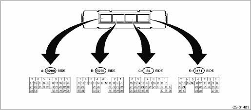
• Model without push button ignition switch
Item | Connector No. | Terminal No. | Input/Output signal |
Measured value and measuring conditions | |||
Battery power supply | B281 | 6 | 9 — 16 V |
7 | |||
i84 | 6 | ||
Ignition power supply | B280 | 32 | 10 — 15 V when ignition switch is at ACC. |
B281 | 3 | 10 — 15 V when ignition switch is at ON or START. | |
TCM (“P” range) | B281 | 20 | Can not be measured because of digital communication |
28 | |||
Stop light and brake switch | B280 | 10 | 9 — 16 V when the stop light & brake switch is ON. 0 V when the stop light & brake switch is OFF. |
“P” range switch | B281 | 18 | Less than 1.5 V when select lever is in “P” range 8 V or more when select lever is in positions other than “P” range. |
Solenoid unit signal | B281 | 5 | 8.5 — 16 V when shift lock is released. 0 V when shift lock is operating. |
Key warning switch signal | B280 | 4 | 9 — 16 V when key is inserted. 0 V when key is removed. |
Key lock solenoid signal | B281 | 4 | 7.5 — 16 V when the key is inserted with the select lever shifted in positions other than “P” range. 0 V at other conditions than above. |
Ground | B280 | 1 | — |
i84 | 1 | ||
Delivery (test) mode signal | i84 | 27 | Can not be measured because of digital communication |
35 |
• Model with push button ignition switch
Item | Connector No. | Terminal No. | Input/Output signal |
Measured value and measuring conditions | |||
Battery power supply | B281 | 6 | 9 — 16 V |
7 | |||
i84 | 6 | ||
Ignition power supply | B280 | 32 | 10 — 15 V when ignition switch is at ACC. |
B281 | 3 | 10 — 15 V when ignition switch is at ON or START. | |
TCM (“P” range) | B281 | 20 | Can not be measured because of digital communication |
28 | |||
Stop light and brake switch | B280 | 10 | 9 — 16 V when the stop light & brake switch is ON. 0 V when the stop light & brake switch is OFF. |
“P” range switch | B281 | 18 | Less than 1.5 V when select lever is in “P” range 8 V or more when select lever is in positions other than “P” range. |
Solenoid unit signal | B281 | 5 | 8.5 — 16 V when shift lock is released. 0 V when shift lock is operating. |
Ground | B280 | 1 | — |
i84 | 1 | ||
Delivery (test) mode signal | i84 | 27 | Can not be measured because of digital communication |
35 |

 Inspection
CONTROL SYSTEMS > AT Shift Lock Control SystemINSPECTION1. SHIFT LOCK OPERATION• Model without push button ignition switchSTEPCHECKYESNO1.CHECK COMMUNICATION OF SUBARU SELECT MONITOR.1) Turn ...
Other materials:
Connecting a smartphone
If you connect a smartphone to this
system after starting a supported aha
application on the smartphone, you can
display and operate the aha application
displayed on the smartphone on the
system screen.
1. Run the aha application on your
smartphone.
2. Connect the iPhone/iPod touch to th ...
Dtc b1408 meter non-volatile memory
IMMOBILIZER (DIAGNOSTICS) > Diagnostic Procedure with Diagnostic Trouble Code (DTC)DTC B1408 METER NON-VOLATILE MEMORYDTC DETECTING CONDITION:Defective combination meterCAUTION:When the combination meter is replaced, registration of the immobilizer system is required. For details, refer to the &l ...
Dtc u1500 keyless uart com. Malfunction
BODY CONTROL SYSTEM (DIAGNOSTICS) > Diagnostic Procedure with Diagnostic Trouble Code (DTC)DTC U1500 KEYLESS UART COM. MALFUNCTION1. MODEL WITHOUT KEYLESS ACCESS WITH PUSH BUTTON START SYSTEMDTC detecting condition:UART between the TPMS & keyless control module or keyless entry CM and the bod ...
