Subaru Crosstrek Service Manual: Electrical component location Location
AIRBAG SYSTEM (DIAGNOSTICS) > Electrical Component Location
LOCATION
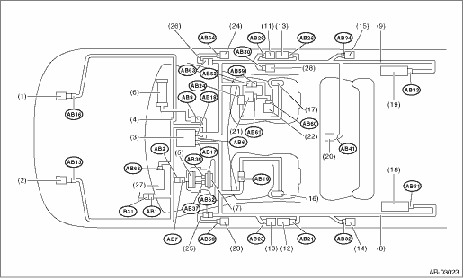
(1) | Front sub sensor (RH) | (11) | Side airbag sensor (RH) | (20) | Satellite safing sensor |
(2) | Front sub sensor (LH) | (12) | Seat belt pretensioner (LH) | (21) | Occupant detection control module |
(3) | Airbag control module | (13) | Seat belt pretensioner (RH) | (22) | Buckle switch (RH) |
(4) | Airbag main harness | (14) | Curtain airbag sensor (LH) | (23) | Front door impact sensor (LH) |
(5) | Roll connector | (15) | Curtain airbag sensor (RH) | (24) | Front door impact sensor (RH) |
(6) | Passenger’s airbag inflator | (16) | Side airbag inflator (LH) | (25) | Door harness (LH) |
(7) | Driver’s airbag inflator | (17) | Side airbag inflator (RH) | (26) | Door harness (RH) |
(8) | Airbag rear harness (LH) | (18) | Curtain airbag inflator (LH) | (27) | Knee airbag inflator |
(9) | Airbag rear harness (RH) | (19) | Curtain airbag inflator (RH) | (28) | Lap seat belt pretensioner (RH) |
(10) | Side airbag sensor (LH) |
Connector No. | (AB1) | (AB2) | (AB6) | (AB7) | (AB9) | (AB13) | (AB16) | (AB17) | (AB18) | (AB19) | (AB21) | (AB23) |
Pin | 10 | 4 | 30 | 4 | 4 | 2 | 2 | 24 | 24 | 4 | 2 | 4 |
Color | Gray | Yellow | Yellow | Yellow | Yellow | Yellow | Yellow | Yellow | Yellow | Yellow | Black | Yellow |
Male/Female | Female | Female | Female | Male | Female | Female | Female | Female | Female | Female | Female | Female |
Connector No. | (AB24) | (AB26) | (AB28) | (AB30) | (AB31) | (AB32) | (AB33) | (AB34) | (AB37) | (AB38) | (AB41) | (AB53) |
Pin | 4 | 2 | 4 | 2 | 2 | 4 | 2 | 4 | 2 | 2 | 2 | 3 |
Color | Yellow | Black | Yellow | Yellow | Black | Yellow | Black | Yellow | Orange | Black | Yellow | Brown |
Male/Female | Female | Female | Female | Female | Female | Female | Female | Female | Female | Female | Female | Female |
Connector No. | (AB58) | (AB59) | (AB60) | (AB61) | (AB62) | (AB63) | (AB64) | (AB66) | ||||
Pin | 2 | 3 | 2 | 10 | 2 | 2 | 2 | 2 | ||||
Color | Yellow | Brown | Yellow | Black | Yellow | Yellow | Yellow | Black | ||||
Male/Female | Female | Male | Male | Female | Female | Female | Female | Female | ||||
 Clear memory mode Operation
AIRBAG SYSTEM (DIAGNOSTICS) > Clear Memory ModeOPERATION1. On «Start» display, select «Diagnosis».2. On «Vehicle selection» display, input the target vehicle information and select «Confirme ...
 Event record data Operation
AIRBAG SYSTEM (DIAGNOSTICS) > Event Record DataOPERATION1. On «Start» display, select «Diagnosis».2. On «Vehicle selection» display, input the target vehicle information and select «Confirme ...
Other materials:
Dtc p0890 tcm power relay sense circuit low
CONTINUOUSLY VARIABLE TRANSMISSION (DIAGNOSTICS) > Diagnostic Procedure with Diagnostic Trouble Code (DTC)DTC P0890 TCM POWER RELAY SENSE CIRCUIT LOWDTC detecting condition:Immediately at fault recognitionTrouble symptom:Gear is not changed.CAUTION:• After diagnosis, perform Clear Memory Mo ...
Electrical specification
INSTRUMENTATION/DRIVER INFO > Multi-function Display (MFD) SystemELECTRICAL SPECIFICATION1. MULTI FUNCTION DISPLAY• Standard typeTerminal No.ItemMeasuring conditionStandard1 (+B) ←> Chassis groundVoltageAlways10 — 14 V2 (GND) ←> Chassis groundResistanceAlwaysLess than 1 ?3 ...
General scan tool Operation
ENGINE (DIAGNOSTICS)(H4DO) > General Scan ToolOPERATION1. HOW TO USE GENERAL SCAN TOOL1. Prepare a scan tool (general scan tool) required by SAE J1978.2. Connect the general scan tool to data link connector located in the lower portion of the instrument panel (on the driver’s side).3. Using ...
