Subaru Crosstrek Service Manual: Dtc p219a bank 1 air-fuel ratio imbalance
ENGINE (DIAGNOSTICS)(H4DO) > Diagnostic Procedure with Diagnostic Trouble Code (DTC)
DTC P219A BANK 1 AIR-FUEL RATIO IMBALANCE
DTC detecting condition:
Detected when two consecutive driving cycles with fault occur.
Trouble symptom:
• Engine stall
• Improper idling
CAUTION:
After servicing or replacing faulty parts, perform Clear Memory Mode Clear Memory Mode > OPERATION"> , and Inspection Mode Inspection Mode > PROCEDURE">.
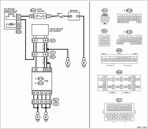
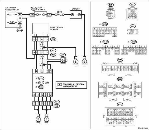
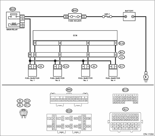
Wiring diagram:
Engine electrical system Engine Electrical System">
| STEP | CHECK | YES | NO |
1.CHECK FRONT OXYGEN (A/F) SENSOR CONNECTOR AND COUPLING CONNECTOR.
Has water entered the connector?
Completely remove any water inside.
Diagnostic Procedure with Diagnostic Trouble Code (DTC) > DTC P219A BANK 1 AIR-FUEL RATIO IMBALANCE">Go to Step 2.
2.CHECK HARNESS BETWEEN ECM AND FRONT OXYGEN (A/F) SENSOR CONNECTOR.
1) Turn the ignition switch to OFF.
2) Disconnect the connector from ECM.
3) Disconnect the connectors from front oxygen (A/F) sensor.
4) Measure the resistance of harness between ECM connector and front oxygen (A/F) sensor connector.
Connector & terminal
(B136) No. 19 — (E24) No. 3:
(B136) No. 18 — (E24) No. 4:
Is the resistance less than 1 ??
Diagnostic Procedure with Diagnostic Trouble Code (DTC) > DTC P219A BANK 1 AIR-FUEL RATIO IMBALANCE">Go to Step 3.
Repair the harness and connector.
NOTE:
In this case, repair the following item:
• Open circuit in harness between ECM connector and front oxygen (A/F) sensor connector
• Poor contact of coupling connector
3.CHECK HARNESS BETWEEN ECM AND FRONT OXYGEN (A/F) SENSOR CONNECTOR.
Measure the resistance between ECM connector and chassis ground.
Connector & terminal
(B136) No. 19 — Chassis ground:
(B136) No. 18 — Chassis ground:
Is the resistance 1 M? or more?
Diagnostic Procedure with Diagnostic Trouble Code (DTC) > DTC P219A BANK 1 AIR-FUEL RATIO IMBALANCE">Go to Step 4.
Repair the short circuit to ground in harness between ECM connector and front oxygen (A/F) sensor connector.
4.CHECK OUTPUT SIGNAL FOR ECM.
1) Connect the connector to ECM.
2) Turn the ignition switch to ON.
3) Measure the voltage between front oxygen (A/F) sensor connector and chassis ground.
Connector & terminal
(E24) No. 3 (+) — Chassis ground (−):
Is the voltage 4.5 V or more?
Diagnostic Procedure with Diagnostic Trouble Code (DTC) > DTC P219A BANK 1 AIR-FUEL RATIO IMBALANCE">Go to Step 6.
Diagnostic Procedure with Diagnostic Trouble Code (DTC) > DTC P219A BANK 1 AIR-FUEL RATIO IMBALANCE">Go to Step 5.
5.CHECK OUTPUT SIGNAL FOR ECM.
Measure the voltage between front oxygen (A/F) sensor connector and chassis ground.
Connector & terminal
(E24) No. 4 (+) — Chassis ground (−):
Is the voltage 4.95 V or more?
Diagnostic Procedure with Diagnostic Trouble Code (DTC) > DTC P219A BANK 1 AIR-FUEL RATIO IMBALANCE">Go to Step 6.
Diagnostic Procedure with Diagnostic Trouble Code (DTC) > DTC P219A BANK 1 AIR-FUEL RATIO IMBALANCE">Go to Step 7.
6.CHECK OUTPUT SIGNAL FOR ECM.
Measure the voltage between front oxygen (A/F) sensor connector and chassis ground.
Connector & terminal
(E24) No. 3 (+) — Chassis ground (−):
(E24) No. 4 (+) — Chassis ground (−):
Is the voltage 8 V or more?
Repair the short circuit to power in the harness between ECM connector and front oxygen (A/F) sensor connector. After repair, replace the ECM. Engine Control Module (ECM)">
Repair the poor contact of ECM connector.
7.CHECK EXHAUST SYSTEM.
Are there holes or loose bolts on exhaust system?
Repair the exhaust system.
Diagnostic Procedure with Diagnostic Trouble Code (DTC) > DTC P219A BANK 1 AIR-FUEL RATIO IMBALANCE">Go to Step 8.
8.CHECK AIR INTAKE SYSTEM.
Are there holes, loose bolts or disconnection of hose on air intake system?
Repair the air intake system.
Diagnostic Procedure with Diagnostic Trouble Code (DTC) > DTC P219A BANK 1 AIR-FUEL RATIO IMBALANCE">Go to Step 9.
9.CHECK FUEL PRESSURE.
WARNING:
Place “NO OPEN FLAMES” signs near the working area.
CAUTION:
Be careful not to spill fuel.
1) Connect the front oxygen (A/F) sensor connector.
2) Measure the fuel pressure. Fuel Pressure > INSPECTION">
CAUTION:
Release fuel pressure before removing the fuel pressure gauge.
Is the measured value 340 — 400 kPa (3.5 — 4.1 kg/cm2, 49 — 58 psi)?
Diagnostic Procedure with Diagnostic Trouble Code (DTC) > DTC P219A BANK 1 AIR-FUEL RATIO IMBALANCE">Go to Step 10.
Check the fuel pump and fuel delivery line. Fuel Pump > INSPECTION"> Fuel Delivery and Evaporation Lines > INSPECTION">
10.CHECK ENGINE COOLANT TEMPERATURE SENSOR.
1) Start the engine and warm up completely.
2) Read the value of «Coolant Temp.» using the Subaru Select Monitor or a general scan tool.
NOTE:
• Subaru Select Monitor
For detailed operation procedures, refer to “Current Data Display For Engine”. Subaru Select Monitor">
• General scan tool
For detailed operation procedures, refer to the general scan tool operation manual.
Is the value of «Coolant Temp.» 75°C (167°F) or more?
Diagnostic Procedure with Diagnostic Trouble Code (DTC) > DTC P219A BANK 1 AIR-FUEL RATIO IMBALANCE">Go to Step 11.
Replace the engine coolant temperature sensor. Engine Coolant Temperature Sensor">
11.CHECK MASS AIR FLOW AND INTAKE AIR TEMPERATURE SENSOR.
1) Start the engine and warm up engine until coolant temperature is higher than 75°C (167°F).
2) For AT models, set the select lever to “P” range or “N” range, and for MT models, place the gear shift lever in the neutral position.
3) Turn the A/C switch to OFF.
4) Turn all the accessory switches to OFF.
5) Read the value of «Mass Air Flow» using the Subaru Select Monitor or a general scan tool.
NOTE:
• Subaru Select Monitor
For detailed operation procedures, refer to “Current Data Display For Engine”. Subaru Select Monitor">
• General scan tool
For detailed operation procedures, refer to the general scan tool operation manual.
Is the value of «Mass Air Flow» 2.0 — 5.0 g/s (0.26 — 0.66 lb/m)?
Diagnostic Procedure with Diagnostic Trouble Code (DTC) > DTC P219A BANK 1 AIR-FUEL RATIO IMBALANCE">Go to Step 12.
Replace the mass air flow and intake air temperature sensor. Mass Air Flow and Intake Air Temperature Sensor">
12.CHECK MASS AIR FLOW AND INTAKE AIR TEMPERATURE SENSOR.
1) Start the engine and warm up engine until coolant temperature is higher than 75°C (167°F).
2) For AT models, set the select lever to “P” range or “N” range, and for MT models, place the gear shift lever in the neutral position.
3) Turn the A/C switch to OFF.
4) Turn all the accessory switches to OFF.
5) Open the front hood.
6) Measure the ambient temperature.
7) Read the value of «Intake Air Temp.» using the Subaru Select Monitor or a general scan tool.
NOTE:
• Subaru Select Monitor
For detailed operation procedures, refer to “Current Data Display For Engine”. Subaru Select Monitor">
• General scan tool
For detailed operation procedures, refer to the general scan tool operation manual.
Subtract ambient temperature from «Intake Air Temp.». Is the obtained value −10 — 50°C (−18 — 90°F)?
Diagnostic Procedure with Diagnostic Trouble Code (DTC) > DTC P219A BANK 1 AIR-FUEL RATIO IMBALANCE">Go to Step 13.
Check the mass air flow and intake air temperature sensor. Mass Air Flow and Intake Air Temperature Sensor">
13.CHECK REAR OXYGEN SENSOR DATA.
1) Warm up the engine until engine coolant temperature is higher than 75°C (167°F), and keep the engine speed at 3,000 rpm. (2 minutes maximum)
2) Read the value of «Rear O2 Sensor Voltage» using the Subaru Select Monitor or a general scan tool.
NOTE:
• Depress the clutch pedal (MT model)
• Subaru Select Monitor
For detailed operation procedures, refer to “Current Data Display For Engine”. Subaru Select Monitor">
• General scan tool
For detailed operation procedures, refer to the general scan tool operation manual.
Is the value of «Rear O2 Sensor Voltage» 0.490 V or more?
Diagnostic Procedure with Diagnostic Trouble Code (DTC) > DTC P219A BANK 1 AIR-FUEL RATIO IMBALANCE">Go to Step 14.
Diagnostic Procedure with Diagnostic Trouble Code (DTC) > DTC P219A BANK 1 AIR-FUEL RATIO IMBALANCE">Go to Step 15.
14.CHECK REAR OXYGEN SENSOR DATA.
1) Warm up the engine until engine coolant temperature is higher than 75°C (167°F), and rapidly reduce the engine speed from 3,000 rpm.
2) Read the value of «Rear O2 Sensor Voltage» using the Subaru Select Monitor or a general scan tool.
NOTE:
• Depress the clutch pedal (MT model)
• Subaru Select Monitor
For detailed operation procedures, refer to “Current Data Display For Engine”. Subaru Select Monitor">
• General scan tool
For detailed operation procedures, refer to the general scan tool operation manual.
Is the value of «Rear O2 Sensor Voltage» 0.250 V or less?
Diagnostic Procedure with Diagnostic Trouble Code (DTC) > DTC P219A BANK 1 AIR-FUEL RATIO IMBALANCE">Go to Step 16.
Diagnostic Procedure with Diagnostic Trouble Code (DTC) > DTC P219A BANK 1 AIR-FUEL RATIO IMBALANCE">Go to Step 15.
15.CHECK REAR OXYGEN SENSOR CONNECTOR AND COUPLING CONNECTOR.
Has water entered the connector?
Completely remove any water inside.
Diagnostic Procedure with Diagnostic Trouble Code (DTC) > DTC P219A BANK 1 AIR-FUEL RATIO IMBALANCE">Go to Step 17.
16.CHECK FRONT OXYGEN (A/F) SENSOR USING REAR OXYGEN SENSOR SIGNAL.
1) Warm up the engine until engine coolant temperature is higher than 75°C (167°F), then keep the engine idling for 5 minutes or more.
2) Read the value of «Rear O2 Sensor Voltage» using the Subaru Select Monitor or a general scan tool.
NOTE:
• Subaru Select Monitor
For detailed operation procedures, refer to “Current Data Display For Engine”. Subaru Select Monitor">
• General scan tool
For detailed operation procedures, refer to the general scan tool operation manual.
Is the value in «Rear O2 Sensor Voltage» kept at 0.250 V or less for 5 minutes or more?
Replace the front oxygen (A/F) sensor. Front Oxygen (A/F) Sensor">
Diagnostic Procedure with Diagnostic Trouble Code (DTC) > DTC P219A BANK 1 AIR-FUEL RATIO IMBALANCE">Go to Step 17.
17.CHECK HARNESS BETWEEN ECM AND REAR OXYGEN SENSOR CONNECTOR.
1) Turn the ignition switch to OFF.
2) Disconnect the connector from ECM.
3) Disconnect the connector from rear oxygen sensor.
4) Measure the resistance of harness between ECM connector and rear oxygen sensor connector.
Connector & terminal
(B136) No. 21 — (E25) No. 3:
(B135) No. 30 — (E25) No. 4:
Is the resistance less than 1 ??
Diagnostic Procedure with Diagnostic Trouble Code (DTC) > DTC P219A BANK 1 AIR-FUEL RATIO IMBALANCE">Go to Step 18.
Repair the harness and connector.
NOTE:
In this case, repair the following item:
• Open circuit in harness between ECM connector and rear oxygen sensor connector
• Poor contact of coupling connector
18.CHECK HARNESS BETWEEN ECM AND REAR OXYGEN SENSOR CONNECTOR.
1) Connect the connector to ECM.
2) Turn the ignition switch to ON.
3) Measure the voltage between rear oxygen sensor connector and chassis ground.
Connector & terminal
(E25) No. 3 (+) — Chassis ground (−):
Is the voltage 0.2 — 0.5 V?
Replace the rear oxygen sensor. Rear Oxygen Sensor">
Diagnostic Procedure with Diagnostic Trouble Code (DTC) > DTC P219A BANK 1 AIR-FUEL RATIO IMBALANCE">Go to Step 19.
19.CHECK OUTPUT SIGNAL OF ECM.
1) Turn the ignition switch to ON.
2) Measure the voltage between ECM and chassis ground on faulty cylinders.
Connector & terminal
#1 (B134) No. 12 (+) — Chassis ground (−):
#2 (B134) No. 22 (+) — Chassis ground (−):
#3 (B134) No. 32 (+) — Chassis ground (−):
#4 (B134) No. 13 (+) — Chassis ground (−):
Is the voltage 10 V or more?
Diagnostic Procedure with Diagnostic Trouble Code (DTC) > DTC P219A BANK 1 AIR-FUEL RATIO IMBALANCE">Go to Step 24.
Diagnostic Procedure with Diagnostic Trouble Code (DTC) > DTC P219A BANK 1 AIR-FUEL RATIO IMBALANCE">Go to Step 20.
20.CHECK HARNESS BETWEEN ECM AND FUEL INJECTOR CONNECTOR.
1) Turn the ignition switch to OFF.
2) Disconnect the connector from fuel injector on faulty cylinders.
3) Measure the resistance between fuel injector connector and engine ground on faulty cylinders.
Connector & terminal
#1 (E5) No. 1 — Engine ground:
#2 (E16) No. 1 — Engine ground:
#3 (E6) No. 1 — Engine ground:
#4 (E17) No. 1 — Engine ground:
Is the resistance 1 M? or more?
Diagnostic Procedure with Diagnostic Trouble Code (DTC) > DTC P219A BANK 1 AIR-FUEL RATIO IMBALANCE">Go to Step 21.
Repair the short circuit to ground in harness between ECM connector and fuel injector connector.
21.CHECK HARNESS BETWEEN ECM AND FUEL INJECTOR CONNECTOR.
Measure the resistance of harness between ECM and fuel injector connector on faulty cylinders.
Connector & terminal
#1 (B134) No. 12 — (E5) No. 1:
#2 (B134) No. 22 — (E16) No. 1:
#3 (B134) No. 32 — (E6) No. 1:
#4 (B134) No. 13 — (E17) No. 1:
Is the resistance less than 1 ??
Diagnostic Procedure with Diagnostic Trouble Code (DTC) > DTC P219A BANK 1 AIR-FUEL RATIO IMBALANCE">Go to Step 22.
Repair the harness and connector.
NOTE:
In this case, repair the following item:
• Open circuit in harness between ECM connector and fuel injector connector
• Poor contact of coupling connector
22.CHECK FUEL INJECTOR.
Measure the resistance between fuel injector terminals on faulty cylinder.
Terminals
No. 1 — No. 2:
Is the resistance 5 — 20 ??
Diagnostic Procedure with Diagnostic Trouble Code (DTC) > DTC P219A BANK 1 AIR-FUEL RATIO IMBALANCE">Go to Step 23.
Replace the faulty fuel injector. Fuel Injector">
23.CHECK POWER SUPPLY LINE.
1) Turn the ignition switch to ON.
2) Measure the voltage between fuel injector connector of faulty cylinders and engine ground.
Connector & terminal
#1 (E5) No. 2 (+) — Engine ground (−):
#2 (E16) No. 2 (+) — Engine ground (−):
#3 (E6) No. 2 (+) — Engine ground (−):
#4 (E17) No. 2 (+) — Engine ground (−):
Is the voltage 10 V or more?
Repair the poor contact of all connectors in fuel injector circuit.
Repair the harness and connector.
NOTE:
In this case, repair the following item:
• Open circuit in harness between the main relay and fuel injector connector on faulty cylinders
• Poor contact of coupling connector
• Poor contact of main relay connector
24.CHECK HARNESS BETWEEN ECM AND FUEL INJECTOR CONNECTOR.
1) Turn the ignition switch to OFF.
2) Disconnect the connector from fuel injector on faulty cylinders.
3) Turn the ignition switch to ON.
4) Measure the voltage between ECM and chassis ground on faulty cylinders.
Connector & terminal
#1 (B134) No. 12 (+) — Chassis ground (−):
#2 (B134) No. 22 (+) — Chassis ground (−):
#3 (B134) No. 32 (+) — Chassis ground (−):
#4 (B134) No. 13 (+) — Chassis ground (−):
Is the voltage 10 V or more?
Repair the short circuit to power in harness between ECM connector and fuel injector connectors.
Diagnostic Procedure with Diag
 Dtc p0851 park/neutral switch input circuit low
ENGINE (DIAGNOSTICS)(H4DO) > Diagnostic Procedure with Diagnostic Trouble Code (DTC)DTC P0851 PARK/NEUTRAL SWITCH INPUT CIRCUIT LOW1. AT MODELDTC detecting condition:Detected when two consecutive d ...
 Dtc p0852 park/neutral switch input circuit high
ENGINE (DIAGNOSTICS)(H4DO) > Diagnostic Procedure with Diagnostic Trouble Code (DTC)DTC P0852 PARK/NEUTRAL SWITCH INPUT CIRCUIT HIGH1. AT MODELDTC detecting condition:Detected when two consecutive ...
Other materials:
Inspection
MANUAL TRANSMISSION AND DIFFERENTIAL(5MT) > Center DifferentialINSPECTION1. Ball bearingReplace the bearings in the following cases.• In case of broken or rusty bearings• In case of worn or damaged bearings• When the bearings fail to turn smoothly or emit noise in rotation after ...
Dtc p0134 a/f / o2 sensor circuit no activity detected bank 1 sensor 1
ENGINE (DIAGNOSTICS)(H4DO) > Diagnostic Procedure with Diagnostic Trouble Code (DTC)DTC P0134 A/F / O2 SENSOR CIRCUIT NO ACTIVITY DETECTED BANK 1 SENSOR 1DTC detecting condition:Immediately at fault recognitionCAUTION:After servicing or replacing faulty parts, perform Clear Memory Mode Clear Mem ...
Dtc p0014 "b" camshaft position - timing over-advanced or system performance bank 1
ENGINE (DIAGNOSTICS)(H4DO) > Diagnostic Procedure with Diagnostic Trouble Code (DTC)DTC P0014 "B" CAMSHAFT POSITION - TIMING OVER-ADVANCED OR SYSTEM PERFORMANCE BANK 1DTC detecting condition:Detected when two consecutive driving cycles with fault occur.Trouble symptom:• Engine sta ...
