Subaru Crosstrek Service Manual: Dtc p2195 a/f /o2 sensor signal biased/stuck lean bank 1 sensor 1
ENGINE (DIAGNOSTICS)(H4DO) > Diagnostic Procedure with Diagnostic Trouble Code (DTC)
DTC P2195 A/F /O2 SENSOR SIGNAL BIASED/STUCK LEAN BANK 1 SENSOR 1
DTC detecting condition:
Detected when two consecutive driving cycles with fault occur.
CAUTION:
After servicing or replacing faulty parts, perform Clear Memory Mode Clear Memory Mode > OPERATION"> , and Inspection Mode Inspection Mode > PROCEDURE">.
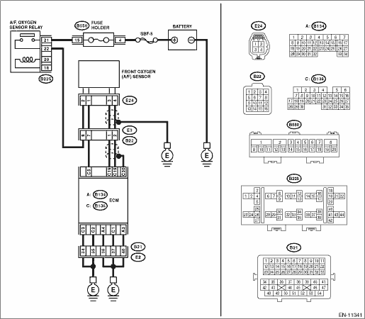
Wiring diagram:
Engine electrical system Engine Electrical System">
| STEP | CHECK | YES | NO |
1.CHECK FRONT OXYGEN (A/F) SENSOR CONNECTOR AND COUPLING CONNECTOR.
Has water entered the connector?
Completely remove any water inside.
Diagnostic Procedure with Diagnostic Trouble Code (DTC) > DTC P2195 A/F /O2 SENSOR SIGNAL BIASED/STUCK LEAN BANK 1 SENSOR 1">Go to Step 2.
2.CHECK HARNESS BETWEEN ECM AND FRONT OXYGEN (A/F) SENSOR CONNECTOR.
1) Turn the ignition switch to OFF.
2) Disconnect the connector from ECM.
3) Disconnect the connectors from front oxygen (A/F) sensor.
4) Measure the resistance of harness between ECM connector and front oxygen (A/F) sensor connector.
Connector & terminal
(B136) No. 19 — (E24) No. 3:
(B136) No. 18 — (E24) No. 4:
Is the resistance less than 1 ??
Diagnostic Procedure with Diagnostic Trouble Code (DTC) > DTC P2195 A/F /O2 SENSOR SIGNAL BIASED/STUCK LEAN BANK 1 SENSOR 1">Go to Step 3.
Repair the harness and connector.
NOTE:
In this case, repair the following item:
• Open circuit in harness between ECM connector and front oxygen (A/F) sensor connector
• Poor contact of coupling connector
3.CHECK FOR POOR CONTACT.
Check for poor contact of the front oxygen (A/F) sensor connector.
Is there poor contact of front oxygen (A/F) sensor connector?
Repair the poor contact of front oxygen (A/F) sensor connector.
Replace the front oxygen (A/F) sensor. Front Oxygen (A/F) Sensor">
1. OUTLINE OF DIAGNOSIS
Detect that λ value remains low.
Judge as NG when lambda value is abnormal in accordance with λ value of front oxygen (A/F) sensor and running conditions such as vehicle speed, amount of intake air, engine coolant temperature, sub feedback control, etc.
λ value = Actual air fuel ratio/Theoretical air fuel ratio |
λ > 1: Lean |
λ < 1: Rich |
2. COMPONENT DESCRIPTION
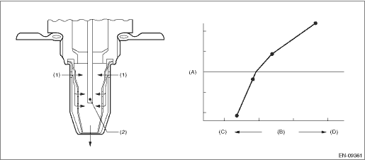
(A) | Electromotive force | (B) | Air fuel ratio | (C) | Rich |
(D) | Lean | ||||
(1) | Exhaust gas | (2) | Zirconia element oxygen |
3. EXECUTION CONDITION
Secondary parameters | Execution condition |
Battery voltage | ≥ 10.9 V |
Barometric pressure | > 75.1 kPa (563 mmHg, 22.2 inHg) |
Main feedback | In operation |
Amount of intake air | ≥ 6 g/s (0.21 oz/s) |
Estimated temperature of the rear oxygen sensor element | ≥ 500 °C (932 °F) |
4. GENERAL DRIVING CYCLE
Perform the diagnosis continuously during driving.
5. DIAGNOSTIC METHOD
If the duration of time while the following conditions are met is longer than the time indicated, judge as NG.
Malfunction Criteria | Threshold Value |
λ value | > 1.15 |
Output voltage value of rear oxygen sensor | > 0.7 V |
Time needed for diagnosis: 10000 ms
Malfunction indicator light illumination: Illuminates when malfunction occurs in 2 continuous driving cycles.
 Dtc p2138 throttle/pedal position sensor/switch "d"/"e" voltage correlation
ENGINE (DIAGNOSTICS)(H4DO) > Diagnostic Procedure with Diagnostic Trouble Code (DTC)DTC P2138 THROTTLE/PEDAL POSITION SENSOR/SWITCH "D"/"E" VOLTAGE CORRELATIONDTC DETECTING COND ...
 Dtc p2196 a/f /o2 sensor signal biased/stuck rich bank 1 sensor 1
ENGINE (DIAGNOSTICS)(H4DO) > Diagnostic Procedure with Diagnostic Trouble Code (DTC)DTC P2196 A/F /O2 SENSOR SIGNAL BIASED/STUCK RICH BANK 1 SENSOR 1DTC DETECTING CONDITION:Detected when two consec ...
Other materials:
Assembly
CONTINUOUSLY VARIABLE TRANSMISSION(TR580) > Transfer ClutchASSEMBLY1. Install the transfer clutch piston.NOTE:Apply CVTF to the transfer clutch piston lip.2. Install the return spring.3. Install the transfer clutch piston seal.NOTE:Apply CVTF to the lip section of transfer clutch piston seal.4. C ...
Removal
FUEL INJECTION (FUEL SYSTEMS)(H4DO) > Engine Control Module (ECM)REMOVAL1. Disconnect the ground cable from battery.2. Remove the glove box. Glove Box > REMOVAL">3. Disconnect the connector from ECM.4. Remove the bolts and nuts, and remove the ECM. ...
Assembly
COOLING(H4DO) > Radiator Main Fan and Fan MotorASSEMBLYAssemble in the reverse order of disassembly.Tightening torque:4.41 N·m (0.45 kgf-m, 3.25 ft-lb)Tightening torque:3.4 N·m (0.3 kgf-m, 2.5 ft-lb) ...
