Subaru Crosstrek Service Manual: Dtc p1530 battery current sensor circuit low
ENGINE (DIAGNOSTICS)(H4DO) > Diagnostic Procedure with Diagnostic Trouble Code (DTC)
DTC P1530 BATTERY CURRENT SENSOR CIRCUIT LOW
DTC detecting condition:
Immediately at fault recognition
CAUTION:
After servicing or replacing faulty parts, perform Clear Memory Mode Clear Memory Mode > OPERATION"> , and Inspection Mode Inspection Mode > PROCEDURE">.
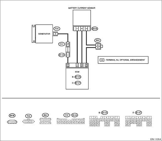
Wiring diagram:
Engine electrical system Engine Electrical System">
| STEP | CHECK | YES | NO |
1.CHECK CURRENT DATA.
1) Start the engine.
2) Read the value of «Battery current value» using the Subaru Select Monitor.
NOTE:
For detailed operation procedures, refer to “Current Data Display For Engine”. Subaru Select Monitor">
Is the value of «Battery current value» −100 A or less?
Diagnostic Procedure with Diagnostic Trouble Code (DTC) > DTC P1530 BATTERY CURRENT SENSOR CIRCUIT LOW">Go to Step 2.
Even if DTC is detected, the circuit has returned to a normal condition at this time. Reproduce the failure, and then perform the diagnosis again.
NOTE:
In this case, temporary poor contact of connector, temporary open or short circuit of harness may be the cause.
2.CHECK HARNESS BETWEEN ECM AND BATTERY CURRENT SENSOR CONNECTOR.
1) Turn the ignition switch to OFF.
2) Disconnect the connector from ECM.
3) Disconnect the connector from the battery current sensor.
4) Measure the resistance of the harness between ECM connector and battery current sensor connector.
Connector & terminal
(B135) No. 22 — (B538) No. 3:
(B137) No. 11 — (B538) No. 1:
Is the resistance less than 1 ??
Diagnostic Procedure with Diagnostic Trouble Code (DTC) > DTC P1530 BATTERY CURRENT SENSOR CIRCUIT LOW">Go to Step 3.
Repair the open circuit in the harness between ECM connector and battery current sensor connector.
3.CHECK HARNESS BETWEEN ECM AND BATTERY CURRENT SENSOR CONNECTOR.
Measure the resistance between ECM connector and chassis ground.
Connector & terminal
(B135) No. 22 — Chassis ground:
(B137) No. 11 — Chassis ground:
Is the resistance 1 M? or more?
Diagnostic Procedure with Diagnostic Trouble Code (DTC) > DTC P1530 BATTERY CURRENT SENSOR CIRCUIT LOW">Go to Step 4.
Repair the short circuit to ground in the harness between ECM connector and battery current sensor connector.
4.CHECK FOR POOR CONTACT.
Check for poor contact between the ECM and battery current sensor connectors.
Is there poor contact of the ECM or battery current sensor connectors?
Repair any poor contact between the ECM and battery current sensor connectors.
Replace the battery current sensor. Battery Current & Temperature Sensor">
1. OUTLINE OF DIAGNOSIS
Detect the open or short circuit of battery current sensor.
Judge as NG if out of specification.
2. COMPONENT DESCRIPTION
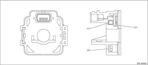
(1) | Hall IC | (2) | Chip condenser | (3) | Core |
3. EXECUTION CONDITION
Secondary Parameters | Execution condition |
Battery voltage | ≥ 10.9 V |
Elapsed time after starting the engine | > 1000 ms |
Engine speed | > 500 rpm |
Ignition switch | ON |
4. GENERAL DRIVING CYCLE
Always perform the diagnosis continuously.
5. DIAGNOSTIC METHOD
If the duration of time while the following conditions are met is longer than the time indicated, judge as NG.
Malfunction Criteria | Threshold Value |
Output voltage | < 0.2148 V |
Time Needed for Diagnosis: 500 ms
Malfunction Indicator Light Illumination: Does not illuminate even when malfunction occurs.
 Dtc p0517 battery temperature sensor circuit high
ENGINE (DIAGNOSTICS)(H4DO) > Diagnostic Procedure with Diagnostic Trouble Code (DTC)DTC P0517 BATTERY TEMPERATURE SENSOR CIRCUIT HIGHDTC detecting condition:Immediately at fault recognitionCAUTION: ...
 Dtc p1531 battery current sensor circuit high
ENGINE (DIAGNOSTICS)(H4DO) > Diagnostic Procedure with Diagnostic Trouble Code (DTC)DTC P1531 BATTERY CURRENT SENSOR CIRCUIT HIGHDTC detecting condition:Immediately at fault recognitionCAUTION:Afte ...
Other materials:
Adjustment
SECURITY AND LOCKS > Front Hood Lock AssemblyADJUSTMENT1. Loosen the bolt, and adjust the lock assembly - front hood while moving it up and down.2. After adjustment, tighten the bolts securely.Tightening torque:Refer to “COMPONENT” of “General Description”. General Descri ...
Removal
CONTROL SYSTEMS > Select LeverREMOVAL1. Shift the select lever to “N” range.2. Disconnect the ground cable from battery. NOTE">NOTE:For model with battery sensor, disconnect the ground terminal from battery sensor.3. Lift up the vehicle.4. Remove the center exhaust pipe. Cen ...
List of diagnostic trouble code (dtc) List
LAN SYSTEM (DIAGNOSTICS) > List of Diagnostic Trouble Code (DTC)LISTDTCItemContent of diagnosisNoteU1201CAN-HS COUNTER ABNORMALHigh speed CAN communication error Diagnostic Procedure with Diagnostic Trouble Code (DTC) > DTC U1201 CAN-HS COUNTER ABNORMAL">U0073CONTROL MODULE COMMUNICATI ...
