Subaru Crosstrek Service Manual: Dtc p0951 auto shift manual control circuit range/performance
CONTINUOUSLY VARIABLE TRANSMISSION (DIAGNOSTICS) > Diagnostic Procedure with Diagnostic Trouble Code (DTC)
DTC P0951 AUTO SHIFT MANUAL CONTROL CIRCUIT RANGE/PERFORMANCE
DTC detecting condition:
Immediately at fault recognition
Trouble symptom:
Manual mode can not be set.
CAUTION:
Use the check board when measuring the TCM terminal voltage and resistance.
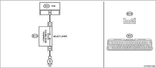
Wiring diagram:
CVT control system CVT Control System">

| STEP | CHECK | YES | NO |
1.CHECK HARNESS.
1) Turn the ignition switch to OFF.
2) Disconnect the manual mode switch connector.
3) Measure the resistance between manual mode switch connector and chassis ground.
Connector & terminal
(B116) No. 8 — Chassis ground:
Is the resistance less than 1 ??
Diagnostic Procedure with Diagnostic Trouble Code (DTC) > DTC P0951 AUTO SHIFT MANUAL CONTROL CIRCUIT RANGE/PERFORMANCE">Go to Step 2.
Repair the open circuit of harness.
2.CHECK MANUAL MODE SWITCH.
Measure the resistance between manual mode switch terminals.
Terminals
No. 7 — No. 8:
Is the resistance 1 M? or more?
Diagnostic Procedure with Diagnostic Trouble Code (DTC) > DTC P0951 AUTO SHIFT MANUAL CONTROL CIRCUIT RANGE/PERFORMANCE">Go to Step 3.
Replace the select lever assembly. Select Lever">
3.CHECK MANUAL MODE SWITCH.
1) Shift the select lever to manual mode.
2) Measure the resistance between manual mode switch terminals.
Terminals
No. 7 — No. 8:
Is the resistance less than 1 ??
Diagnostic Procedure with Diagnostic Trouble Code (DTC) > DTC P0951 AUTO SHIFT MANUAL CONTROL CIRCUIT RANGE/PERFORMANCE">Go to Step 4.
Replace the select lever assembly. Select Lever">
4.CHECK HARNESS.
1) Disconnect the TCM connector.
2) Measure the resistance between TCM connector and manual mode switch connector.
Connector & terminal
(B54) No. 20 — (B116) No. 7:
Is the resistance less than 1 ??
Diagnostic Procedure with Diagnostic Trouble Code (DTC) > DTC P0951 AUTO SHIFT MANUAL CONTROL CIRCUIT RANGE/PERFORMANCE">Go to Step 5.
Repair the open circuit of harness or poor contact of connector.
5.CHECK HARNESS.
Measure the resistance between manual mode switch connector and chassis ground.
Connector & terminal
(B116) No. 7 — Chassis ground:
Is the resistance 1 M? or more?
Diagnostic Procedure with Diagnostic Trouble Code (DTC) > DTC P0951 AUTO SHIFT MANUAL CONTROL CIRCUIT RANGE/PERFORMANCE">Go to Step 6.
Repair the short circuit of harness.
6.CHECK INPUT SIGNAL FOR TCM.
1) Connect all connectors.
2) Turn the ignition switch to ON.
3) Set the select lever to “D” range.
4) Read the data of «Tiptronic Mode Switch» using Subaru Select Monitor.
Does the value of «Tiptronic Mode Switch» change to “ON” with select lever in manual mode, and “OFF” with select lever in other than manual mode?
Current condition is normal.
Diagnostic Procedure with Diagnostic Trouble Code (DTC) > DTC P0951 AUTO SHIFT MANUAL CONTROL CIRCUIT RANGE/PERFORMANCE">Go to Step 7.
7.CHECK FOR POOR CONTACT.
Is there poor contact of the manual mode switch circuit?
Repair the poor contact.
Replace the TCM. Transmission Control Module (TCM)">
1. OUTLINE OF DIAGNOSIS
• Detect the GND-output short (ground-fault) in manual SW circuit.
• Judge as NG if the manual SW is ON in P, R or N range.
2. EXECUTION CONDITION
Secondary parameters | Execution condition |
None |
3. DIAGNOSTIC METHOD
If the duration of time while the following conditions are met is longer than the time indicated, judge as NG.
Malfunction Criteria | Threshold Value |
Manual SW status in other than D range | ON |
Time Needed for Diagnosis: 5 s
Malfunction Indicator Light Illumination: Does not illuminate.
 Dtc p0890 tcm power relay sense circuit low
CONTINUOUSLY VARIABLE TRANSMISSION (DIAGNOSTICS) > Diagnostic Procedure with Diagnostic Trouble Code (DTC)DTC P0890 TCM POWER RELAY SENSE CIRCUIT LOWDTC detecting condition:Immediately at fault rec ...
 Dtc p0961 pressure control solenoid "a" control circuit range/performance
CONTINUOUSLY VARIABLE TRANSMISSION (DIAGNOSTICS) > Diagnostic Procedure with Diagnostic Trouble Code (DTC)DTC P0961 PRESSURE CONTROL SOLENOID "A" CONTROL CIRCUIT RANGE/PERFORMANCEDTC DETE ...
Other materials:
Inspection
POWER ASSISTED SYSTEM (POWER STEERING) > Universal JointINSPECTIONCheck for wear, damage or any other faults.1. Check the universal joint assembly - steering for excessive looseness.Service limit:Play of the universal joint assembly - steering: 0 mm (0 in)2. Measure the swing torque of the univer ...
Removal
HVAC SYSTEM (HEATER, VENTILATOR AND A/C) > FRESH/RECIRC Door ActuatorREMOVALCAUTION:Before handling the airbag system components, refer to “CAUTION” of “General Description” in “AIRBAG SYSTEM”. General Description > CAUTION">1. Disconnect the ground ...
Ground circuit Wiring diagram
WIRING SYSTEM > Ground CircuitWIRING DIAGRAM ...
