Subaru Crosstrek Service Manual: Dtc p0890 tcm power relay sense circuit low
CONTINUOUSLY VARIABLE TRANSMISSION (DIAGNOSTICS) > Diagnostic Procedure with Diagnostic Trouble Code (DTC)
DTC P0890 TCM POWER RELAY SENSE CIRCUIT LOW
DTC detecting condition:
Immediately at fault recognition
Trouble symptom:
Gear is not changed.
CAUTION:
• After diagnosis, perform Clear Memory Mode for ECM. Clear Memory Mode">
• Use the check board when measuring the TCM terminal voltage and resistance.
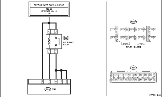
Wiring diagram:
CVT control system CVT Control System">

| STEP | CHECK | YES | NO |
1.CHECK HARNESS.
1) Disconnect the TCM connector.
2) Remove the self shut relay.
3) Measure the resistance between TCM connector and relay holder.
Connector & terminal
(B54) No. 25 — (B220) No. 16:
(B54) No. 8 — (B220) No. 15:
(B54) No. 24 — (B220) No. 15:
(B54) No. 40 — (B220) No. 15:
Is the resistance less than 1 ??
Diagnostic Procedure with Diagnostic Trouble Code (DTC) > DTC P0890 TCM POWER RELAY SENSE CIRCUIT LOW">Go to Step 2.
Repair the open circuit of harness.
2.CHECK HARNESS.
Measure the resistance between TCM connector and chassis ground.
Connector & terminal
(B54) No. 25 — Chassis ground:
(B54) No. 8 — Chassis ground:
(B54) No. 24 — Chassis ground:
(B54) No. 40 — Chassis ground:
Is the resistance 1 M? or more?
Diagnostic Procedure with Diagnostic Trouble Code (DTC) > DTC P0890 TCM POWER RELAY SENSE CIRCUIT LOW">Go to Step 3.
Repair the short circuit of harness.
3.CHECK RELAY POWER SUPPLY.
Measure the voltage between relay holder and chassis ground.
Connector & terminal
(B220) No. 14 (+) — Chassis ground (−):
(B220) No. 17 (+) — Chassis ground (−):
Is the voltage 11 — 13 V or more?
Diagnostic Procedure with Diagnostic Trouble Code (DTC) > DTC P0890 TCM POWER RELAY SENSE CIRCUIT LOW">Go to Step 4.
Repair the open or short circuit of harness.
4.CHECK SELF SHUT RELAY.
Measure the resistance between self shut relay terminals.
Terminals
No. 16 — No. 17:
Is the resistance 110 — 140 ??
Diagnostic Procedure with Diagnostic Trouble Code (DTC) > DTC P0890 TCM POWER RELAY SENSE CIRCUIT LOW">Go to Step 5.
Replace the self shut relay.
5.CHECK SELF SHUT RELAY.
Measure the resistance between self shut relay terminals.
Terminals
No. 14 — No. 15:
Is the resistance 1 M? or more?
Diagnostic Procedure with Diagnostic Trouble Code (DTC) > DTC P0890 TCM POWER RELAY SENSE CIRCUIT LOW">Go to Step 6.
Replace the self shut relay.
6.CHECK INPUT SIGNAL FOR TCM.
1) Connect the TCM connector.
2) Install the self shut relay.
3) Read the data of «Control module voltage» using Subaru Select Monitor.
Is the «Control module voltage» 10 V or more?
Current condition is normal. Check for poor contact in connectors or harnesses, and repair the defective part.
Diagnostic Procedure with Diagnostic Trouble Code (DTC) > DTC P0890 TCM POWER RELAY SENSE CIRCUIT LOW">Go to Step 7.
7.CHECK SELF SHUT RELAY.
1) Turn the ignition switch to OFF.
2) Replace the self shut relay.
3) Perform the Clear Memory Mode. Clear Memory Mode">
4) Read the DTC.
Is DTC P0890 displayed?
Replace the TCM. Transmission Control Module (TCM)">
The original self shut relay is defective.
1. OUTLINE OF DIAGNOSIS
• Detect the malfunction of transmission fluid pressure solenoid drive power supply relay circuit.
• Judge as NG if the transmission fluid pressure solenoid drive power supply voltage is lower than the predetermined value.
2. EXECUTION CONDITION
Secondary Parameters | Execution condition |
12 V battery system voltage | ≥ 9 V |
Ignition state | Run or Crank |
3. DIAGNOSTIC METHOD
If the duration of time while the following conditions are met is longer than the time indicated, judge as NG.
Malfunction Criteria | Threshold Value |
Measured TCM input voltage which is supplied from 12 V battery system through the TCM Power Relay | < 2 V |
Time Needed for Diagnosis: 0.5 seconds
Malfunction Indicator Light Illumination: Illuminates as soon as a malfunction occurs.
 Dtc p0843 transmission fluid pressure sensor/switch "a" circuit high
CONTINUOUSLY VARIABLE TRANSMISSION (DIAGNOSTICS) > Diagnostic Procedure with Diagnostic Trouble Code (DTC)DTC P0843 TRANSMISSION FLUID PRESSURE SENSOR/SWITCH "A" CIRCUIT HIGHDTC detecting ...
 Dtc p0951 auto shift manual control circuit range/performance
CONTINUOUSLY VARIABLE TRANSMISSION (DIAGNOSTICS) > Diagnostic Procedure with Diagnostic Trouble Code (DTC)DTC P0951 AUTO SHIFT MANUAL CONTROL CIRCUIT RANGE/PERFORMANCEDTC detecting condition:Immedi ...
Other materials:
Assembly
CONTINUOUSLY VARIABLE TRANSMISSION(TR580) > Forward Clutch AssemblyASSEMBLY1. FORWARD CLUTCH ASSEMBLY1. Install the forward clutch piston to forward clutch drum.NOTE:• Apply CVTF to the seal of forward clutch piston.• Insert it all the way to the end.2. Install the return spring.3. In ...
Manual transmission, front differential and rear differential gear oil
*1: The indicated oil quantity is only a guideline. The necessary quantity
for replacement may differ slightly depending on the temperature and other
factors. After refilling the gearbox with oil, the oil level should be checked.
*2: For more details about maintenance and service, refer to ...
Assembly
CONTINUOUSLY VARIABLE TRANSMISSION(TR580) > Oil Pump ChainASSEMBLY1. DRIVE SPROCKET1. Using the ST, install the ball bearing.NOTE:Use a new ball bearing.ST 499755502PRESS SNAP RING2. Install the snap ring. ...
