Subaru Crosstrek Service Manual: Dtc p0708 transmission range sensor "a" circuit high
CONTINUOUSLY VARIABLE TRANSMISSION (DIAGNOSTICS) > Diagnostic Procedure with Diagnostic Trouble Code (DTC)
DTC P0708 TRANSMISSION RANGE SENSOR "A" CIRCUIT HIGH
DTC detecting condition:
Immediately at fault recognition
Trouble symptom:
• Shift characteristics are erroneous.
• The range position of the select lever and the position of shift indicator display do not match.
CAUTION:
Use the check board when measuring the TCM terminal voltage and resistance.
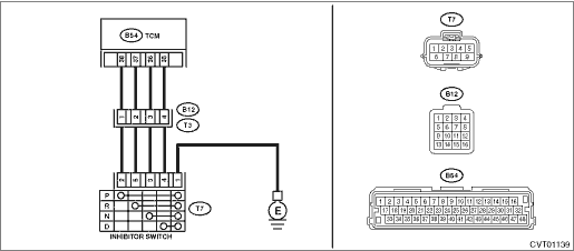
Wiring diagram:
CVT control system CVT Control System">

| STEP | CHECK | YES | NO |
1.CHECK INPUT SIGNAL FOR TCM.
1) Turn the ignition switch to ON.
2) Move the select lever to each range, and read the data of «P Range», «R Range Signal», «N Range» and «D Range Signal» using the Subaru Select Monitor.
Is the display of the corresponding range “ON”?
Diagnostic Procedure with Diagnostic Trouble Code (DTC) > DTC P0708 TRANSMISSION RANGE SENSOR "A" CIRCUIT HIGH">Go to Step 7.
Diagnostic Procedure with Diagnostic Trouble Code (DTC) > DTC P0708 TRANSMISSION RANGE SENSOR "A" CIRCUIT HIGH">Go to Step 2.
2.CHECK HARNESS.
1) Turn the ignition switch to OFF.
2) Disconnect the TCM connector.
3) Disconnect the transmission connector.
4) Measure the resistance of harness between TCM connector and transmission connector.
Connector & terminal
(B54) No. 38 — (B12) No. 1:
(B54) No. 37 — (B12) No. 2:
(B54) No. 36 — (B12) No. 3:
(B54) No. 35 — (B12) No. 4:
Is each resistance less than 1 ??
Diagnostic Procedure with Diagnostic Trouble Code (DTC) > DTC P0708 TRANSMISSION RANGE SENSOR "A" CIRCUIT HIGH">Go to Step 3.
Repair the open circuit of body harness.
3.CHECK HARNESS.
Measure the resistance of harness between inhibitor switch connector and transmission ground.
Connector & terminal
(T7) No. 1 — Transmission ground:
Is the resistance less than 1 ??
Diagnostic Procedure with Diagnostic Trouble Code (DTC) > DTC P0708 TRANSMISSION RANGE SENSOR "A" CIRCUIT HIGH">Go to Step 4.
Repair the open circuit of harness.
4.CHECK HARNESS.
1) Disconnect the inhibitor switch connector.
2) Measure the resistance between transmission connector and inhibitor switch connector.
Connector & terminal
(T3) No. 1 — (T7) No. 2:
(T3) No. 2 — (T7) No. 5:
(T3) No. 3 — (T7) No. 3:
(T3) No. 4 — (T7) No. 4:
Is each resistance less than 1 ??
Diagnostic Procedure with Diagnostic Trouble Code (DTC) > DTC P0708 TRANSMISSION RANGE SENSOR "A" CIRCUIT HIGH">Go to Step 5.
Repair the open circuit of transmission harness.
5.CHECK INHIBITOR SWITCH.
Move the select lever to each range, and measure the resistance between inhibitor switch terminals.
Terminals
No. 2 — No. 1:
No. 5 — No. 1:
No. 3 — No. 1:
No. 4 — No. 1:
Is the resistance of the corresponding range less than 1 M??
Diagnostic Procedure with Diagnostic Trouble Code (DTC) > DTC P0708 TRANSMISSION RANGE SENSOR "A" CIRCUIT HIGH">Go to Step 6.
Replace the inhibitor switch. Inhibitor Switch">
6.CHECK HARNESS.
1) Turn the ignition switch to ON.
2) Measure the voltage between each connector and chassis ground.
Connector & terminal
Transmission connector (B12 side)
(B12) No. 1 (+) — Chassis ground (−):
(B12) No. 2 (+) — Chassis ground (−):
(B12) No. 3 (+) — Chassis ground (−):
(B12) No. 4 (+) — Chassis ground (−):
Transmission connector (T7 side)
(T7) No. 2 (+) — Chassis ground (−):
(T7) No. 5 (+) — Chassis ground (−):
(T7) No. 3 (+) — Chassis ground (−):
(T7) No. 4 (+) — Chassis ground (−):
Is each voltage less than 1 V?
Diagnostic Procedure with Diagnostic Trouble Code (DTC) > DTC P0708 TRANSMISSION RANGE SENSOR "A" CIRCUIT HIGH">Go to Step 7.
Repair the harness which outputs 1 V or more.
7.CHECK FOR POOR CONTACT.
Is there poor contact between TCM, inhibitor switch, transmission ground?
Repair the poor contact.
Replace the TCM. Transmission Control Module (TCM)">
1. OUTLINE OF DIAGNOSIS
• Detect the malfunction of Range Switch.
• Judge as NG if there is no input from all Range Switches.
2. EXECUTION CONDITION
Secondary Parameters | Execution condition |
12 V battery system voltage | ≥ 10 V |
Vehicle speed (calculated from secondary pulley shaft speed) | ≥ 6 MPH |
3. DIAGNOSTIC METHOD
If the duration of time while the following conditions are met is longer than the time indicated, judge as NG.
Malfunction Criteria | Threshold Value |
All transmission range switches OFF NOTE: |
“Transmission range switch OFF” is defined as transmission range switch input voltage ≥ 3.4 V.
True
Time Needed for Diagnosis: 3 seconds
Malfunction Indicator Light Illumination: Illuminates as soon as a malfunction occurs.
 Dtc p0705 transmission range sensor "a" circuit (prndl input)
CONTINUOUSLY VARIABLE TRANSMISSION (DIAGNOSTICS) > Diagnostic Procedure with Diagnostic Trouble Code (DTC)DTC P0705 TRANSMISSION RANGE SENSOR "A" CIRCUIT (PRNDL INPUT)DTC detecting condit ...
 Dtc p0711 transmission fluid temperature sensor "a" circuit range/performance
CONTINUOUSLY VARIABLE TRANSMISSION (DIAGNOSTICS) > Diagnostic Procedure with Diagnostic Trouble Code (DTC)DTC P0711 TRANSMISSION FLUID TEMPERATURE SENSOR "A" CIRCUIT RANGE/PERFORMANCEDTC ...
Other materials:
Component
FUEL INJECTION (FUEL SYSTEMS)(H4DO) > General DescriptionCOMPONENT1. INTAKE MANIFOLD 1(1)Intake manifold protector(7)GasketTightening torque: N·m (kgf-m, ft-lb)(2)Cap(8)Tumble generator valve actuatorT1:3.4 (0.3, 2.5)(3)Manifold absolute pressure sensor(9)Tumble generator valve RHT2:6 (0.6 ...
Removal
AIRBAG SYSTEM > Driver’s Airbag ModuleREMOVALCAUTION:Before handling the airbag system components, refer to “CAUTION” of “General Description” in “AIRBAG SYSTEM”. General Description > CAUTION">1. Position the front wheels straight ahead.2. Tu ...
Inspection
EyeSight > Relay and FuseINSPECTION1. CHECK FUSE1. Remove the fuse and inspect visually.2. If the fuse is blown out, replace the fuse.NOTE:If the fuse is blown again, check the system wiring harness.2. CHECK RELAY1. Measure the resistance between relay terminals.Terminal No.Inspection conditionsS ...
