
Subaru Crosstrek Service Manual: Dtc p0560 system voltage
ENGINE (DIAGNOSTICS)(H4DO) > Diagnostic Procedure with Diagnostic Trouble Code (DTC)
DTC P0560 SYSTEM VOLTAGE
DTC DETECTING CONDITION:
Immediately at fault recognition
CAUTION:
After servicing or replacing faulty parts, perform Clear Memory Mode Clear Memory Mode > OPERATION"> , and Inspection Mode Inspection Mode > PROCEDURE">.
WIRING DIAGRAM:
Engine electrical system Engine Electrical System">
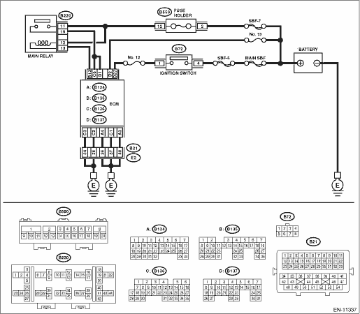
| STEP | CHECK | YES | NO |
1.CHECK INPUT SIGNAL OF ECM.
1) Turn the ignition switch to OFF.
2) Measure the voltage between ECM connector and chassis ground.
Connector & terminal
(B137) No. 2 (+) — Chassis ground (−):
Is the voltage 10 V or more?
Repair the poor contact of ECM connector.
Diagnostic Procedure with Diagnostic Trouble Code (DTC) > DTC P0560 SYSTEM VOLTAGE">Go to Step 2.
2.CHECK HARNESS BETWEEN ECM AND MAIN FUSE BOX CONNECTOR.
1) Disconnect the connector from ECM.
2) Measure the resistance between ECM connector and chassis ground.
Connector & terminal
(B137) No. 2 — Chassis ground:
Is the resistance 1 M? or more?
Diagnostic Procedure with Diagnostic Trouble Code (DTC) > DTC P0560 SYSTEM VOLTAGE">Go to Step 3.
Repair the short circuit to ground in harness between ECM connector and battery terminal.
3.CHECK FUSE NO. 13 (MAIN FUSE BOX).
Is the fuse blown out?
Replace the fuse.
Repair the harness and connector.
NOTE:
In this case, repair the following item:
• Open circuit in harness between ECM connector and battery
• Poor contact of ECM connector
• Poor contact of battery terminal
1. OUTLINE OF DIAGNOSIS
Detect the open/short circuit of back-up power supply circuit.
Judge as NG when the backup power voltage is low.
2. EXECUTION CONDITION
Secondary Parameters | Execution condition |
Battery voltage | ≥ 10.9 V |
3. GENERAL DRIVING CYCLE
Always perform the diagnosis continuously.
4. DIAGNOSTIC METHOD
If the duration of time while the following conditions are met is longer than the time indicated, judge as NG.
Malfunction Criteria | Threshold Value |
Voltage of back-up power supply | ≤ 3.5 V |
Time Needed for Diagnosis: 2500 ms
Malfunction Indicator Light Illumination: Illuminates as soon as a malfunction occurs.
 Dtc p0125 insufficient coolant temperature for closed loop fuel control
ENGINE (DIAGNOSTICS)(H4DO) > Diagnostic Procedure with Diagnostic Trouble Code (DTC)DTC P0125 INSUFFICIENT COOLANT TEMPERATURE FOR CLOSED LOOP FUEL CONTROLDTC detecting condition:Detected when two ...
 Dtc u0122 lost communication with vehicle dynamics control module
ENGINE (DIAGNOSTICS)(H4DO) > Diagnostic Procedure with Diagnostic Trouble Code (DTC)DTC U0122 LOST COMMUNICATION WITH VEHICLE DYNAMICS CONTROL MODULENOTE:For the diagnostic procedure, refer to LAN ...
Other materials:
Installation
FUEL INJECTION (FUEL SYSTEMS)(H4DO) > Fuel PumpINSTALLATION1. Install the fuel pump assembly to the fuel tank.(1) Make sure the sealing portion is free from fuel or foreign matter before installation.(2) Align the protrusion (A) of the gasket to the position shown in the figure, and install the g ...
Assembly
CLUTCH SYSTEM > Clutch PedalASSEMBLY1. Install the stopper and pedal pad to the clutch pedal.2. Install the clutch switch to the pedal bracket.3. Clean the pedal bushing holes of the clutch pedal and the brake pedal, apply grease, and install the pedal bushings.4. Install the clutch pedal, brake ...
Dtc b2a02 tel2 antenna circuit
TELEMATICS SYSTEM (DIAGNOSTICS) > Diagnostic Procedure with Diagnostic Trouble Code (DTC)DTC B2A02 TEL2 ANTENNA CIRCUITDiagnosis start condition:When ignition switch is ON.DTC detecting condition:Any of the followings continues for 5 seconds or more.• TEL2 impedance is more than 1 M?. (Deta ...
