Subaru Crosstrek Service Manual: Dtc p0517 battery temperature sensor circuit high
ENGINE (DIAGNOSTICS)(H4DO) > Diagnostic Procedure with Diagnostic Trouble Code (DTC)
DTC P0517 BATTERY TEMPERATURE SENSOR CIRCUIT HIGH
DTC detecting condition:
Immediately at fault recognition
CAUTION:
After servicing or replacing faulty parts, perform Clear Memory Mode Clear Memory Mode > OPERATION"> , and Inspection Mode Inspection Mode > PROCEDURE">.
Wiring diagram:
Engine electrical system Engine Electrical System">

| STEP | CHECK | YES | NO |
1.CHECK CURRENT DATA.
1) Start the engine.
2) Read the value of «Battery temperature» using the Subaru Select Monitor.
NOTE:
For detailed operation procedures, refer to “Current Data Display For Engine”. Subaru Select Monitor">
Is the value of «Battery temperature» −40°C (−40°F) or less?
Diagnostic Procedure with Diagnostic Trouble Code (DTC) > DTC P0517 BATTERY TEMPERATURE SENSOR CIRCUIT HIGH">Go to Step 2.
Even if DTC is detected, the circuit has returned to a normal condition at this time. Reproduce the failure, and then perform the diagnosis again.
NOTE:
In this case, temporary poor contact of connector, temporary open or short circuit of harness may be the cause.
2.CHECK FOR POOR CONTACT.
Check for poor contact between the ECM and battery temperature sensor connectors.
Is there poor contact of the ECM or battery temperature sensor connectors?
Repair any poor contact between the ECM and battery temperature sensor connectors.
Diagnostic Procedure with Diagnostic Trouble Code (DTC) > DTC P0517 BATTERY TEMPERATURE SENSOR CIRCUIT HIGH">Go to Step 3.
3.CHECK HARNESS BETWEEN ECM AND BATTERY TEMPERATURE SENSOR CONNECTOR.
1) Turn the ignition switch to OFF.
2) Disconnect the connector from ECM.
3) Disconnect the connector from the battery temperature sensor.
4) Measure the resistance of harness between ECM connector and battery temperature sensor connector.
Connector & terminal
(B137) No. 24 — (B523) No. 1:
(B135) No. 30 — (B523) No. 2:
Is the resistance less than 1 ??
Diagnostic Procedure with Diagnostic Trouble Code (DTC) > DTC P0517 BATTERY TEMPERATURE SENSOR CIRCUIT HIGH">Go to Step 4.
Repair the harness and connector.
NOTE:
In this case, repair the following item:
• Open circuit in harness between ECM connector and battery temperature sensor connector
• Poor contact of joint connector
4.CHECK HARNESS BETWEEN ECM AND BATTERY TEMPERATURE SENSOR CONNECTOR.
1) Connect all connectors.
2) Turn the ignition switch to ON.
3) Measure the voltage between ECM connector and chassis ground.
Connector & terminal
(B137) No. 24 (+) — Chassis ground (−):
Is the voltage 5 V or more?
Repair the short circuit to power in harness between ECM connector and battery temperature sensor connector.
Replace the battery temperature sensor. Battery Current & Temperature Sensor">
1. OUTLINE OF DIAGNOSIS
Detect the open or short circuit of battery temperature sensor.
Judge as NG if out of specification.
2. COMPONENT DESCRIPTION
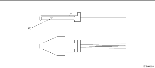
(1) | Sensor element |
3. EXECUTION CONDITION
Secondary Parameters | Execution condition |
Battery voltage | ≥ 10.9 V |
Elapsed time after starting the engine | > 1000 ms |
Engine speed | > 500 rpm |
Ignition switch | ON |
4. GENERAL DRIVING CYCLE
Always perform the diagnosis continuously.
5. DIAGNOSTIC METHOD
If the duration of time while the following conditions are met is longer than the time indicated, judge as NG.
Malfunction Criteria | Threshold Value |
Output voltage | ≥ 4.668 V |
Time Needed for Diagnosis: 500 ms
Malfunction Indicator Light Illumination: Does not illuminate even when malfunction occurs.
 Dtc p0516 battery temperature sensor circuit low
ENGINE (DIAGNOSTICS)(H4DO) > Diagnostic Procedure with Diagnostic Trouble Code (DTC)DTC P0516 BATTERY TEMPERATURE SENSOR CIRCUIT LOWDTC detecting condition:Immediately at fault recognitionCAUTION:A ...
 Dtc p1530 battery current sensor circuit low
ENGINE (DIAGNOSTICS)(H4DO) > Diagnostic Procedure with Diagnostic Trouble Code (DTC)DTC P1530 BATTERY CURRENT SENSOR CIRCUIT LOWDTC detecting condition:Immediately at fault recognitionCAUTION:After ...
Other materials:
Basic operation
By operating "
" or "
" of the control
switch, the screens and selection items
can be switched. When the "
/SET"
switch is pulled toward you, the item can
be selected and set.
If there are some useful messages, such
as vehicle information, warning information,
etc., they wi ...
Inspection
SECURITY AND LOCKS > Rear Lock ButtonINSPECTION1. Using the Subaru Select Monitor, display «Rear gate/Trunk UNLOCK output» from «Data monitor».2. Check if the display changes when the rear lock button is operated.3. If the display is not correct as the result of inspection, refer to “Ge ...
Installation
AIRBAG SYSTEM > Passenger’s Airbag ModuleINSTALLATIONCAUTION:• Before handling the airbag system components, refer to “CAUTION” of “General Description” in “AIRBAG SYSTEM”. General Description > CAUTION">• Do not allow harness and ...
