Subaru Crosstrek Service Manual: Dtc p0327 knock/combustion vibration sensor 1 circuit low bank 1 or single sensor
ENGINE (DIAGNOSTICS)(H4DO) > Diagnostic Procedure with Diagnostic Trouble Code (DTC)
DTC P0327 KNOCK/COMBUSTION VIBRATION SENSOR 1 CIRCUIT LOW BANK 1 OR SINGLE SENSOR
DTC DETECTING CONDITION:
Immediately at fault recognition
TROUBLE SYMPTOM:
• Poor driving performance
• Knocking occurs
CAUTION:
After servicing or replacing faulty parts, perform Clear Memory Mode Clear Memory Mode > OPERATION"> , and Inspection Mode Inspection Mode > PROCEDURE">.
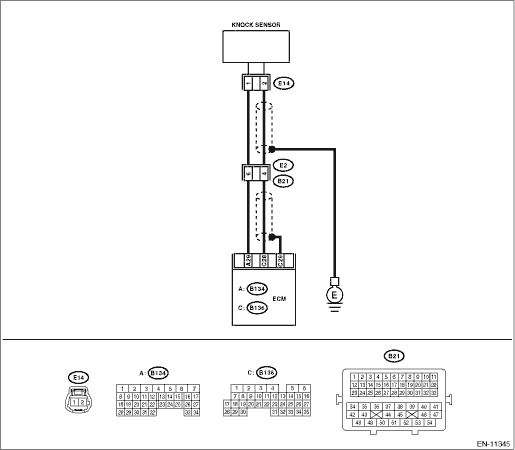
WIRING DIAGRAM:
Engine electrical system Engine Electrical System">
| STEP | CHECK | YES | NO |
1.CHECK HARNESS BETWEEN ECM AND KNOCK SENSOR CONNECTOR.
1) Turn the ignition switch to OFF.
2) Disconnect the connector from ECM.
3) Measure the resistance between ECM connectors.
Connector & terminal
(B136) No. 28 — (B134) No. 29:
Is the resistance less than 500 k??
Diagnostic Procedure with Diagnostic Trouble Code (DTC) > DTC P0327 KNOCK/COMBUSTION VIBRATION SENSOR 1 CIRCUIT LOW BANK 1 OR SINGLE SENSOR">Go to Step 2.
Diagnostic Procedure with Diagnostic Trouble Code (DTC) > DTC P0327 KNOCK/COMBUSTION VIBRATION SENSOR 1 CIRCUIT LOW BANK 1 OR SINGLE SENSOR">Go to Step 3.
2.CHECK KNOCK SENSOR.
1) Disconnect the connector from the knock sensor.
2) Measure the resistance between knock sensor terminals.
Terminals
No. 1 — No. 2:
Is the resistance less than 500 k??
Replace the knock sensor. Knock Sensor">
Repair the short circuit to ground in harness between ECM connector and knock sensor connector.
NOTE:
The harness between both connectors are shielded. Remove the shield and repair the short circuit of harness.
3.CHECK INPUT SIGNAL OF ECM.
1) Connect the connector to ECM.
2) Turn the ignition switch to ON.
3) Measure the voltage between ECM connector and chassis ground.
Connector & terminal
(B136) No. 28 (+) — Chassis ground (−):
Is the voltage 2 V or more?
Even if DTC is detected, the circuit has returned to a normal condition at this time. Reproduce the failure, and then perform the diagnosis again.
NOTE:
In this case, temporary poor contact of connector, temporary open or short circuit of harness may be the cause.
Repair the short circuit to ground in harness between ECM connector and knock sensor connector.
NOTE:
The harness between both connectors are shielded. Remove the shield and repair the short circuit of harness.
1. OUTLINE OF DIAGNOSIS
Detect the open or short circuit of knock sensor.
Judge as NG if out of specification.
2. COMPONENT DESCRIPTION
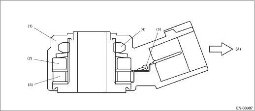
(A) | To knock sensor harness | ||||
(1) | Case | (3) | Piezoelectric element | (5) | Resistance |
(2) | Weight | (4) | Nut |
3. EXECUTION CONDITION
Secondary Parameters | Execution condition |
None |
4. GENERAL DRIVING CYCLE
Always perform the diagnosis continuously.
5. DIAGNOSTIC METHOD
If the duration of time while the following conditions are met is longer than the time indicated, judge as NG.
Malfunction Criteria | Threshold Value |
Output voltage | < 0.154 V |
Time Needed for Diagnosis: 1000 ms
Malfunction Indicator Light Illumination: Illuminates as soon as a malfunction occurs.
 Dtc p0304 cylinder 4 misfire detected
ENGINE (DIAGNOSTICS)(H4DO) > Diagnostic Procedure with Diagnostic Trouble Code (DTC)DTC P0304 CYLINDER 4 MISFIRE DETECTEDDTC detecting condition:• Detected when two consecutive driving cycles ...
 Dtc p0328 knock/combustion vibration sensor 1 circuit high bank 1 or single sensor
ENGINE (DIAGNOSTICS)(H4DO) > Diagnostic Procedure with Diagnostic Trouble Code (DTC)DTC P0328 KNOCK/COMBUSTION VIBRATION SENSOR 1 CIRCUIT HIGH BANK 1 OR SINGLE SENSORDTC DETECTING CONDITION:Immedia ...
Other materials:
Key replacement
Your key number plate will be required if
you ever need a replacement key made.
Any new key must be registered for use
with your vehicle's immobilizer system
before it can be used. The maximum
number of keys that can be registered
for use with one vehicle is as follows.
Four (models with ...
Inspection
SUNROOF/T-TOP/CONVERTIBLE TOP (SUNROOF) > SunshadeINSPECTION1. MOVING LOAD OF SUNSHADE ASSEMBLY1. Attach a spring scale together with a cloth to the edge of sunshade assembly.2. Pull the spring scale to check the moving load of the sunshade assembly.Moving load of sunshade assembly:14±6 N (1.43 ...
Installation
MECHANICAL(H4DO) > Chain CoverINSTALLATION1. Install the O-rings to cylinder head RH, cylinder head LH, cylinder block LH and oil pan upper.NOTE:• Use new O-rings.• Apply a coat of engine oil to the O-rings.2. Apply liquid gasket if there are gaps between front camshaft cap and cam ca ...
