Subaru Crosstrek Service Manual: Dtc c2511 torque sensor main
POWER ASSISTED SYSTEM (POWER STEERING) (DIAGNOSTICS) > Diagnostic Procedure with Diagnostic Trouble Code (DTC)
DTC C2511 TORQUE SENSOR MAIN
Trouble symptom:
• The steering wheel operation feels heavy.
• STEERING warning light illuminates.
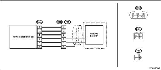
Wiring diagram:
Electric power steering system Electric Power Steering System">
| STEP | CHECK | YES | NO |
1.CHECK TORQUE SENSOR SIGNAL.
1) Display the current data of the power steering control module using the Subaru Select Monitor.
2) Check the voltage of «Torque sensor main output», «Torque sensor sub output», «Torque sensor reference voltage» and «Torque sensor power supply voltage».
Are the voltage of «Torque sensor main output» and «Torque sensor sub output» 2.5±0.1 V?
Is the voltage of «Torque sensor reference voltage» 3±0.1 V?
Is the voltage of «Torque sensor power supply voltage» 8±0.4 V?
Check for poor contact of the connector, and check the conditions again. If the condition recur, go to the next step. Diagnostic Procedure with Diagnostic Trouble Code (DTC) > DTC C2511 TORQUE SENSOR MAIN">Go to Step 2.
If it does not recur, complete the inspection.
Diagnostic Procedure with Diagnostic Trouble Code (DTC) > DTC C2511 TORQUE SENSOR MAIN">Go to Step 2.
2.CHECK HARNESS.
1) Turn the ignition switch to OFF.
2) Disconnect the connectors (B450, B451).
3) Using a tester and test harness, check the internal resistance of the harness terminals.
Connector & terminal
(B450) No. 4 — (B451) No. 3:
(B450) No. 5 — (B451) No. 5:
(B450) No. 8 — (B451) No. 1:
(B450) No. 9 — (B451) No. 2:
(B450) No. 10 — (B451) No. 4:
Is the resistance less than 10 ??
Diagnostic Procedure with Diagnostic Trouble Code (DTC) > DTC C2511 TORQUE SENSOR MAIN">Go to Step 3.
Repair or replace the harness.
3.CHECK POWER STEERING CONTROL MODULE.
1) Connect the connector (B450) to the power steering control module.
2) Turn the ignition switch to ON.
3) Short the circuit between connector (B451) terminals.
Terminals
No. 4 — No. 3:
No. 4 — No. 5:
4) Using the Subaru Select Monitor, check the voltages of «Torque sensor main output» and «Torque sensor sub output».
Are the voltages of «Torque sensor main output» and «Torque sensor sub output» before you short the circuit 0±0.1 V?
Are the voltages of «Torque sensor main output» and «Torque sensor sub output» after you short the circuit 3±0.1 V?
Replace the steering gearbox. Electric Power Steering Gearbox">
Replace the power steering control module. Power Steering Control Module">
 Dtc u0122 lost communication with vehicle dynamics control module
POWER ASSISTED SYSTEM (POWER STEERING) (DIAGNOSTICS) > Diagnostic Procedure with Diagnostic Trouble Code (DTC)DTC U0122 LOST COMMUNICATION WITH VEHICLE DYNAMICS CONTROL MODULENOTE:Refer to “L ...
 Dtc c2512 torque sensor sub
POWER ASSISTED SYSTEM (POWER STEERING) (DIAGNOSTICS) > Diagnostic Procedure with Diagnostic Trouble Code (DTC)DTC C2512 TORQUE SENSOR SUBNOTE:Refer to “DTC C2511 TORQUE SENSOR MAIN” for ...
Other materials:
Inspection
HVAC SYSTEM (HEATER, VENTILATOR AND A/C) > Relay and FuseINSPECTION1. CHECK FUSE1. Remove the fuse and inspect visually.2. If the fuse is blown out, replace the fuse.NOTE:If the fuse is blown again, check the system wiring harness.2. CHECK RELAY1. Check the resistance between relay terminals.&bul ...
Operation
INSTRUMENTATION/DRIVER INFO > Multi-function Display (MFD) SystemOPERATION1. DIAGNOSTIC MODE (HIGH GRADE TYPE ONLY)The settings of the multi-function display can be changed by performing the following procedures to display the diagnostic mode. To show the demonstration display only, refer to &ldq ...
Maintenance schedule
U.S. models
The scheduled maintenance items required
to be serviced at regular intervals
are shown in the "Warranty and Maintenance
Booklet". For details, read the
separate "Warranty and Maintenance
Booklet".
Canada models
The scheduled maintenance items required
to be serviced at regular i ...
