Subaru Crosstrek Service Manual: Dtc b1907 short in front p/t lh (to ground)
AIRBAG SYSTEM (DIAGNOSTICS) > Diagnostic Chart with Trouble Code
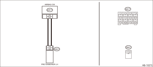
DTC B1907 SHORT IN FRONT P/T LH (TO GROUND)
Diagnosis start condition:
Ignition voltage is 10 V to 16 V.
DTC detecting condition:
• Seat belt pretensioner (LH) circuit is shorted to ground.
• Pretensioner (LH) is faulty.
• Pretensioner harness (LH) is faulty.
• Airbag control module is faulty.
CAUTION:
Before performing diagnosis, refer to “CAUTION” in “General Description”. General Description > CAUTION">
Wiring diagram:
Airbag system Airbag System > WIRING DIAGRAM">
| STEP | CHECK | YES | NO |
1.CHECK POOR CONTACT OF CONNECTORS.
Check for poor contact of the connectors between the airbag control module and the seat belt pretensioner LH.
Is there poor contact?
Replace the airbag rear harness along with body harness.
Diagnostic Chart with Trouble Code > DTC B1907 SHORT IN FRONT P/T LH (TO GROUND)">Go to Step 2.
2.CHECK SEAT BELT PRETENSIONER.
1) Turn the ignition switch to OFF, disconnect the battery ground cable, and wait for 60 seconds or more.
2) Disconnect the connector (AB21) from seat belt pretensioner (LH).
3) Connect the connector (1N) in the test harness N to the connector (AB21).
4) Connect the airbag resistor to the connector (2N) of test harness N.
5) Connect the battery ground terminal and turn the ignition switch to ON.
Does the airbag warning light illuminate for six seconds and go off?
Replace the seat belt pretensioner (LH). Front Seat Belt">
Diagnostic Chart with Trouble Code > DTC B1907 SHORT IN FRONT P/T LH (TO GROUND)">Go to Step 3.
3.CHECK AIRBAG REAR HARNESS (PRETENSIONER HARNESS LH).
1) Turn the ignition switch to OFF, disconnect the battery ground cable, and wait for 60 seconds or more.
2) Disconnect the airbag resistor from the connector (2N) of test harness N.
3) Disconnect connector (AB19) from side airbag module (LH).
4) Disconnect the connector (AB31) from curtain airbag module (LH).
5) Disconnect the connectors (AB6, AB17, AB18) from airbag control module.
6) Connect the connector (1AG) in the test harness AG to the connectors (AB6, AB17, AB18).
7) Measure the resistance between connector (3AG) in the test harness AG and chassis ground.
Connector & terminal
(3AG) No. 10 — Chassis ground:
(3AG) No. 12 — Chassis ground:
Is the resistance 1 M? or more?
Diagnostic Chart with Trouble Code > DTC B1907 SHORT IN FRONT P/T LH (TO GROUND)">Go to Step 4.
Replace the airbag rear harness along with body harness.
4.CHECK AIRBAG CONTROL MODULE.
1) Connect all connectors.
2) Clear the memory. Clear Memory Mode">
3) Perform the Inspection Mode. Inspection Mode">
4) Read the DTC. (Current malfunction) Read Diagnostic Trouble Code (DTC)">
Is DTC B1907 displayed?
Replace the airbag control module. Airbag Control Module">
Diagnostic Chart with Trouble Code > DTC B1907 SHORT IN FRONT P/T LH (TO GROUND)">Go to Step 5.
5.CHECK FOR ANY OTHER DTC ON DISPLAY.
Is any other DTC displayed?
Check DTC using “List of Diagnostic Trouble Code (DTC)”. List of Diagnostic Trouble Code (DTC)">
Finish the diagnosis.
 Dtc b1906 open in front p/t lh
AIRBAG SYSTEM (DIAGNOSTICS) > Diagnostic Chart with Trouble CodeDTC B1906 OPEN IN FRONT P/T LHDiagnosis start condition:Ignition voltage is 10 V to 16 V.DTC detecting condition:• Seat belt pr ...
 Dtc b1610 front sub sensor rh failure
AIRBAG SYSTEM (DIAGNOSTICS) > Diagnostic Chart with Trouble CodeDTC B1610 FRONT SUB SENSOR RH FAILUREDIAGNOSIS START CONDITION:Ignition voltage is 10 V to 16 V.DTC DETECTING CONDITION:Front sub sen ...
Other materials:
Inspection
CONTINUOUSLY VARIABLE TRANSMISSION(TR580) > Primary Speed SensorINSPECTION1. Set the ST between the TCM and bulkhead harness.ST 18460AA040CHECK BOARD2. Set the probe of oscilloscope to the check board connector.Connector & terminalNo. 14 (+) — No. 42 (−):(A)+ probe(B)− probe3 ...
Specifications
Specifications
Dimensions
*1: All measurements for the Subaru Ascent are taken with the vehicle in an unloaded
condition, ensuring standardized reference values.
Engine
Fuel
Engine oil
For complete procedures related to checking, refilling, and replacing engine
oil in your Suba ...
Automatic door locking/unlocking
In the Subaru Ascent, all doors, the rear gate, and the fuel filler lid can be
automatically locked or unlocked based on specific driving conditions. This intelligent
feature enhances both safety and convenience during everyday vehicle operation.
For automatic door locking
In the Subaru A ...
