Subaru Crosstrek Service Manual: Dtc b1822 short in side airbag rh (to ground)
AIRBAG SYSTEM (DIAGNOSTICS) > Diagnostic Chart with Trouble Code
DTC B1822 SHORT IN SIDE AIRBAG RH (TO GROUND)
Diagnosis start condition:
Ignition voltage is 10 V to 16 V.
DTC detecting condition:
• Side airbag harness (RH) circuit is shorted to ground.
• Side airbag module (RH) is faulty.
• Airbag control module is faulty.
CAUTION:
Before performing diagnosis, refer to “CAUTION” in “General Description”. General Description > CAUTION">
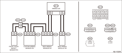
Wiring diagram:
Airbag system Airbag System > WIRING DIAGRAM">
| STEP | CHECK | YES | NO |
1.CHECK POOR CONTACT OF CONNECTORS.
Check for poor contact of the connectors between the airbag control module, side airbag module RH and the side airbag sensor RH.
Is there poor contact?
Replace the airbag rear harness along with body harness.
Diagnostic Chart with Trouble Code > DTC B1822 SHORT IN SIDE AIRBAG RH (TO GROUND)">Go to Step 2.
2.CHECK SIDE AIRBAG MODULE.
1) Turn the ignition switch to OFF, disconnect the battery ground cable, and wait for 60 seconds or more.
2) Disconnect the connector (AB24), and connect the connector (1AJ) in test harness AJ to connector (AB24).
3) Connect the airbag resistor to the test harness AJ connector (3AJ).
4) Connect the battery ground terminal and turn the ignition switch to ON.
Does the airbag warning light illuminate for six seconds and go off?
Replace the side airbag module (RH). Side Airbag Module > REMOVAL">
Diagnostic Chart with Trouble Code > DTC B1822 SHORT IN SIDE AIRBAG RH (TO GROUND)">Go to Step 3.
3.CHECK AIRBAG REAR HARNESS (SIDE AIRBAG MODULE HARNESS RH).
1) Turn the ignition switch to OFF, disconnect the battery ground cable, and wait for 60 seconds or more.
2) Disconnect the connector (AB26) from seat belt pretensioner (RH).
3) Disconnect the connector (AB33) from curtain airbag module (RH).
4) Disconnect the airbag resistor from test harness AJ.
5) Disconnect the connectors (AB6, AB17, AB18) from airbag control module.
6) Connect the connector (1AG) in the test harness AG to the connectors (AB6, AB17, AB18).
7) Measure the resistance between connector (5AG) in the test harness AG and chassis ground.
Connector & terminal
(5AG) No. 5 — Chassis ground:
(5AG) No. 7 — Chassis ground:
Is the resistance 1 M? or more?
Diagnostic Chart with Trouble Code > DTC B1822 SHORT IN SIDE AIRBAG RH (TO GROUND)">Go to Step 4.
Replace the airbag rear harness along with body harness.
4.CHECK AIRBAG CONTROL MODULE.
1) Connect all connectors.
2) Clear the memory. Clear Memory Mode">
3) Perform the Inspection Mode. Inspection Mode">
4) Read the DTC. (Current malfunction) Read Diagnostic Trouble Code (DTC)">
Is DTC B1822 displayed?
Replace the airbag control module. Airbag Control Module">
Diagnostic Chart with Trouble Code > DTC B1822 SHORT IN SIDE AIRBAG RH (TO GROUND)">Go to Step 5.
5.CHECK FOR ANY OTHER DTC ON DISPLAY.
Is any other DTC displayed?
Check DTC using “List of Diagnostic Trouble Code (DTC)”. List of Diagnostic Trouble Code (DTC)">
Finish the diagnosis.
 Dtc b1821 open in side airbag rh
AIRBAG SYSTEM (DIAGNOSTICS) > Diagnostic Chart with Trouble CodeDTC B1821 OPEN IN SIDE AIRBAG RHDiagnosis start condition:Ignition voltage is 10 V to 16 V.DTC detecting condition:• Side airba ...
 Dtc b1823 short in side airbag rh (to +b)
AIRBAG SYSTEM (DIAGNOSTICS) > Diagnostic Chart with Trouble CodeDTC B1823 SHORT IN SIDE AIRBAG RH (TO +B)Diagnosis start condition:Ignition voltage is 10 V to 16 V.DTC detecting condition:• S ...
Other materials:
Regarding radio wave
WARNING
If you wear an implanted pacemaker
or an implanted defibrillator, stay at
least 8.7 in (22 cm) away from the
transmitting antennas installed on
the vehicle.
The radio waves from the transmitting
antennas on the vehicle could
adversely affect the operation of
implanted pacemakers a ...
Check list for interview Check
INSTRUMENTATION/DRIVER INFO (DIAGNOSTICS) > Check List for InterviewCHECK• Inspect the following items regarding the vehicle’s state.• Print out this page for interviewing customers.Combination Meter / MFD Check List for Interview Date the ...
Preparation tool
CONTROL SYSTEMS > General DescriptionPREPARATION TOOL1. SPECIAL TOOLILLUSTRATIONTOOL NUMBERDESCRIPTIONREMARKS — SUBARU SELECT MONITOR 4Used for setting of each function and troubleshooting for electrical system.NOTE:For detailed operation procedures of Subaru Select Monitor 4, refer to “A ...
