Subaru Crosstrek Service Manual: Dtc b1647 side satellite sensor bus lh lost communication
AIRBAG SYSTEM (DIAGNOSTICS) > Diagnostic Chart with Trouble Code
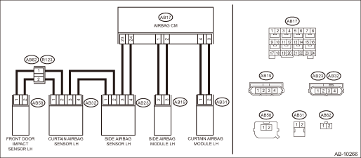
DTC B1647 SIDE SATELLITE SENSOR BUS LH LOST COMMUNICATION
Diagnosis start condition:
Ignition voltage is 10 V to 16 V.
DTC detecting condition:
• Open or short circuit in harness of side sensor bus (LH)
• Side airbag sensor (LH) is faulty.
• Curtain airbag sensor (LH) is faulty.
• Front door impact sensor (LH) is faulty.
• Airbag control module is faulty.
CAUTION:
Before performing diagnosis, refer to “CAUTION” in “General Description”. General Description > CAUTION">
Wiring diagram:
Airbag system Airbag System > WIRING DIAGRAM">
| STEP | CHECK | YES | NO |
1.CHECK DTC.
Read the DTC. (Current malfunction) Read Diagnostic Trouble Code (DTC)">
Is DTC B1627 or B1628 displayed?
Perform the diagnosis according to DTC.
Diagnostic Chart with Trouble Code > DTC B1647 SIDE SATELLITE SENSOR BUS LH LOST COMMUNICATION">Go to Step 2.
2.CHECK DTC.
Read the DTC. (Current malfunction) Read Diagnostic Trouble Code (DTC)">
Is DTC B1637 or B1638 displayed?
Perform the diagnosis according to DTC.
Diagnostic Chart with Trouble Code > DTC B1647 SIDE SATELLITE SENSOR BUS LH LOST COMMUNICATION">Go to Step 3.
3.CHECK DTC.
Read the DTC. (Current malfunction) Read Diagnostic Trouble Code (DTC)">
Is DTC B1697 or B1698 displayed?
Perform the diagnosis according to DTC.
Diagnostic Chart with Trouble Code > DTC B1647 SIDE SATELLITE SENSOR BUS LH LOST COMMUNICATION">Go to Step 4.
4.CHECK POOR CONTACT OF CONNECTORS.
Check for poor contact of the connectors between the airbag control module and the front door impact sensor (LH).
Is there poor contact?
Replace the airbag rear harness and the door harness.
Diagnostic Chart with Trouble Code > DTC B1647 SIDE SATELLITE SENSOR BUS LH LOST COMMUNICATION">Go to Step 5.
5.CHECK AIRBAG REAR HARNESS (BETWEEN AIRBAG CONTROL MODULE AND SIDE AIRBAG SENSOR LH).
1) Turn the ignition switch to OFF, disconnect the battery ground cable, and wait for 60 seconds or more.
2) Disconnect the connector (AB21) from seat belt pretensioner (LH).
3) Disconnect the connector (AB31) from curtain airbag module (LH).
4) Disconnect connector (AB19) of the side airbag module (LH).
5) Disconnect the connectors (AB6, AB17, AB18) from airbag control module.
6) Connect the connector (1AG) in the test harness AG to the connectors (AB6, AB17, AB18).
7) Disconnect the connector (AB23) from the side airbag sensor (LH).
8) Connect the connector (2V) in the test harness V to the connector (AB23).
9) Measure the resistance between connector (5AG) in the test harness AG and connector (3V) in the test harness V.
Connector & terminal
(5AG) No. 10 — (3V) No. 1:
(5AG) No. 8 — (3V) No. 2:
Is the resistance less than 10 ??
Diagnostic Chart with Trouble Code > DTC B1647 SIDE SATELLITE SENSOR BUS LH LOST COMMUNICATION">Go to Step 6.
Replace the airbag rear harness along with body harness.
6.CHECK AIRBAG REAR HARNESS (BETWEEN AIRBAG CONTROL MODULE AND SIDE AIRBAG SENSOR LH).
Measure the resistance between connector (3V) in test harness V and chassis ground, and the resistance between connector (3V) terminals.
Connector & terminal
(3V) No. 1 — Chassis ground:
(3V) No. 2 — Chassis ground:
(3V) No. 1 — (3V) No. 2:
Is the resistance 1 M? or more?
Diagnostic Chart with Trouble Code > DTC B1647 SIDE SATELLITE SENSOR BUS LH LOST COMMUNICATION">Go to Step 7.
Replace the airbag rear harness along with body harness.
7.CHECK AIRBAG REAR HARNESS (BETWEEN SIDE AIRBAG SENSOR AND CURTAIN AIRBAG SENSOR LH).
1) Disconnect the connector (2V) in the test harness V from the connector (AB23) of side airbag sensor (LH).
2) Connect the connector (AB23) of side airbag sensor (LH) and the connector (1AI) in the test harness AI.
3) Connect the connector (2AI) in the test harness AI and the connector (1V) in the test harness V.
4) Disconnect the connector (AB32) from curtain airbag sensor (LH), and connect the connector (2V) in test harness V to connector (AB32).
5) Measure the resistance between connector (3V) terminals in the test harness V.
Connector & terminal
(3V) No. 2 — (3V) No. 6:
(3V) No. 1 — (3V) No. 7:
Is the resistance less than 10 ??
Diagnostic Chart with Trouble Code > DTC B1647 SIDE SATELLITE SENSOR BUS LH LOST COMMUNICATION">Go to Step 8.
Replace the airbag rear harness along with body harness.
8.CHECK AIRBAG REAR HARNESS (BETWEEN SIDE AIRBAG SENSOR AND CURTAIN AIRBAG SENSOR LH).
Measure the resistance between connector (3V) in test harness V and chassis ground, and the resistance between connector (3V) terminals in test harness V.
Connector & terminal
(3V) No. 2 — Chassis ground:
(3V) No. 1 — Chassis ground:
(3V) No. 1 — (3V) No. 2:
Is the resistance 1 M? or more?
Diagnostic Chart with Trouble Code > DTC B1647 SIDE SATELLITE SENSOR BUS LH LOST COMMUNICATION">Go to Step 9.
Replace the airbag rear harness along with body harness.
9.CHECK AIRBAG REAR HARNESS AND DOOR HARNESS (BETWEEN CURTAIN AIRBAG SENSOR LH AND DOOR SENSOR LH).
1) Disconnect the connector (AB58) from the front door impact sensor (LH), and connect the connector (1H) in the test harness H to connector (AB58).
2) Measure the resistance between connector (3V) in the test harness V and connector (3H) in the test harness H.
Connector & terminal
(3V) No. 4 — (3H) No. 5:
(3V) No. 5 — (3H) No. 6:
Is the resistance less than 10 ??
Diagnostic Chart with Trouble Code > DTC B1647 SIDE SATELLITE SENSOR BUS LH LOST COMMUNICATION">Go to Step 10.
Check the door harness, and if any fault is found, replace the harness. If there is no fault, replace the airbag rear harness together with body harness.
10.CHECK AIRBAG REAR HARNESS AND DOOR HARNESS (BETWEEN CURTAIN AIRBAG SENSOR LH AND DOOR SENSOR LH).
Measure the resistance between connector (3V) in test harness V and chassis ground, and the resistance between connector (3V) terminals in test harness V.
Connector & terminal
(3V) No. 4 — Chassis ground:
(3V) No. 5 — Chassis ground:
(3V) No. 4 — (3V) No. 5:
Is the resistance 1 M? or more?
Diagnostic Chart with Trouble Code > DTC B1647 SIDE SATELLITE SENSOR BUS LH LOST COMMUNICATION">Go to Step 11.
Check the door harness, and if any fault is found, replace the harness. If there is no fault, replace the airbag rear harness together with body harness.
11.CHECK AIRBAG CONTROL MODULE.
1) Connect all connectors.
2) Clear the memory. Clear Memory Mode">
3) Perform the Inspection Mode. Inspection Mode">
4) Read the DTC. (Current malfunction) Read Diagnostic Trouble Code (DTC)">
Is DTC B1647 displayed?
Diagnostic Chart with Trouble Code > DTC B1647 SIDE SATELLITE SENSOR BUS LH LOST COMMUNICATION">Go to Step 12.
Diagnostic Chart with Trouble Code > DTC B1647 SIDE SATELLITE SENSOR BUS LH LOST COMMUNICATION">Go to Step 15.
12.REPLACE SIDE AIRBAG SENSOR (LH) AND CHECK AIRBAG CONTROL MODULE AFTER REPLACEMENT.
1) Turn the ignition switch to OFF, disconnect the battery ground cable, and wait for 60 seconds or more.
2) Replace the side airbag sensor (LH). Side Airbag Sensor > REMOVAL">
3) Connect all connectors.
4) Clear the memory. Clear Memory Mode">
5) Perform the Inspection Mode. Inspection Mode">
6) Read the DTC. (Current malfunction) Read Diagnostic Trouble Code (DTC)">
Is DTC B1647 displayed?
Diagnostic Chart with Trouble Code > DTC B1647 SIDE SATELLITE SENSOR BUS LH LOST COMMUNICATION">Go to Step 13.
Diagnostic Chart with Trouble Code > DTC B1647 SIDE SATELLITE SENSOR BUS LH LOST COMMUNICATION">Go to Step 15.
13.REPLACE CURTAIN AIRBAG SENSOR (LH) AND CHECK AIRBAG CONTROL MODULE AFTER REPLACEMENT.
1) Turn the ignition switch to OFF, disconnect the battery ground cable, and wait for 60 seconds or more.
2) Replace the curtain airbag sensor (LH). Curtain Airbag Sensor > REMOVAL">
3) Connect all connectors.
4) Clear the memory. Clear Memory Mode">
5) Perform the Inspection Mode. Inspection Mode">
6) Read the DTC. (Current malfunction) Read Diagnostic Trouble Code (DTC)">
Is DTC B1647 displayed?
Diagnostic Chart with Trouble Code > DTC B1647 SIDE SATELLITE SENSOR BUS LH LOST COMMUNICATION">Go to Step 14.
Diagnostic Chart with Trouble Code > DTC B1647 SIDE SATELLITE SENSOR BUS LH LOST COMMUNICATION">Go to Step 15.
14.REPLACE FRONT DOOR IMPACT SENSOR (LH) AND CHECK AIRBAG CONTROL MODULE AFTER REPLACEMENT.
1) Turn the ignition switch to OFF, disconnect the battery ground cable, and wait for 60 seconds or more.
2) Replace the front door impact sensor (LH). Front Door Impact Sensor > REMOVAL">
3) Connect all connectors.
4) Clear the memory. Clear Memory Mode">
5) Perform the Inspection Mode. Inspection Mode">
6) Read the DTC. (Current malfunction) Read Diagnostic Trouble Code (DTC)">
Is DTC B1647 displayed?
Replace the airbag control module. Airbag Control Module > REMOVAL">
Diagnostic Chart with Trouble Code > DTC B1647 SIDE SATELLITE SENSOR BUS LH LOST COMMUNICATION">Go to Step 15.
15.CHECK FOR ANY OTHER DTC ON DISPLAY.
Is any other DTC displayed?
Perform the diagnosis according to DTC.
Finish the diagnosis.
 Dtc b1642 side satellite sensor bus rh lost communication
AIRBAG SYSTEM (DIAGNOSTICS) > Diagnostic Chart with Trouble CodeDTC B1642 SIDE SATELLITE SENSOR BUS RH LOST COMMUNICATIONDiagnosis start condition:Ignition voltage is 10 V to 16 V.DTC detecting con ...
 Dtc b1655 front buckle switch rh failure
AIRBAG SYSTEM (DIAGNOSTICS) > Diagnostic Chart with Trouble CodeDTC B1655 FRONT BUCKLE SWITCH RH FAILURENOTE:Refer to “Occupant Detection System” for details on DTC B1655. Diagnostic P ...
Other materials:
Dtc b28a7 stereo camera recognition(target)
EyeSight (DIAGNOSTICS) > Diagnostic Procedure with Diagnostic Trouble Code (DTC)DTC B28A7 STEREO CAMERA RECOGNITION(TARGET)Detected when error occurs in the communication data inside the control module caused by external factors such as noises.NOTE:If the same DTC is still detected after the engi ...
Operation
INSTRUMENTATION/DRIVER INFO > Combination Meter SystemOPERATION1. SELF-DIAGNOSIS DISPLAY MODEThe self-diagnosis (checking of each meter, warning light, indicator light, illumination, LCD/TFT) of combination meter can be performed in the following procedure.1. ProcedureCAUTION:Perform the steps de ...
Assembly
MANUAL TRANSMISSION AND DIFFERENTIAL(5MT) > Center DifferentialASSEMBLYInstall the ball bearings.CAUTION:Do not apply a load in excess of 10 kN (1 ton, 1.1 US ton, 1.0 Imp ton).NOTE:Use a new ball bearing.(A)Ball bearing ...
