Subaru Crosstrek Service Manual: Disassembly
CONTROL SYSTEMS > MT Gear Shift Lever
DISASSEMBLY
1. Remove the lock wires.
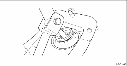
(A) | Lock wire |
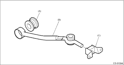
2. Remove the rod from gear shift lever.
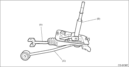
(A) | Rod |
(B) | Lever |
(C) | Stay |
3. Separate the rod and inner boot.
4. Remove the snap ring from the stay.
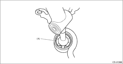
(A) | Snap ring |
5. Separate the gear shift lever and the stay.
6. Remove the boot and bushing from the gear shift lever.
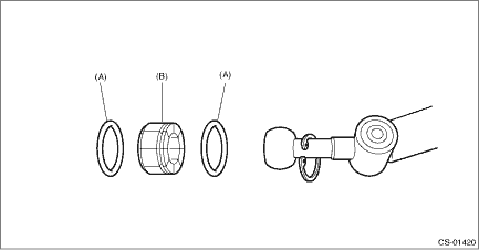
(A) | O-ring |
(B) | Bushing |
7. Remove the spring pin, and then remove the bushing and snap ring.
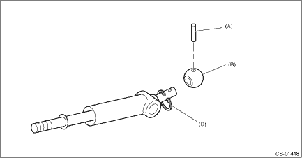
(A) | Spring pin |
(B) | Bushing |
(C) | Snap ring |
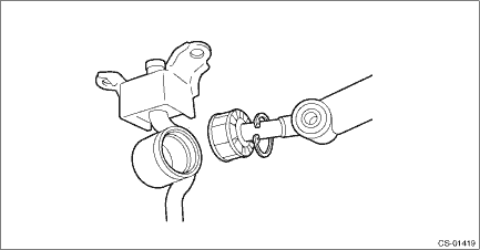
8. Remove the boss from the joint.
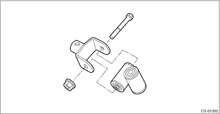
9. Remove the bushing and spacer from the boss.
(A) | Bushing |
(B) | Spacer |
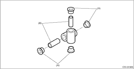
10. Remove the bushing and cushion rubber from the stay.
(A) | Bushing B |
(B) | Stay |
(C) | Cushion rubber |
 Removal
CONTROL SYSTEMS > MT Gear Shift LeverREMOVAL1. Disconnect the ground cable from battery. NOTE">NOTE:For model with battery sensor, disconnect the ground terminal from battery sensor.2. Rem ...
 Inspection
CONTROL SYSTEMS > MT Gear Shift LeverINSPECTION1. Check the parts (bushing, cushion rubber, spacer, boot, stay and rod, etc.) for deformation, damage and wear. If necessary, correct or replace faul ...
Other materials:
Assembly
SEATS > Rear SeatASSEMBLYCAUTION:• Do not reuse hog rings.• Secure the hog ring using hog ring pliers.• Install the hog rings to the specified points securely and make sure that there is no wrinkle or twisting on the cover COMPL - rear backrest.1. Assemble the cover COMPL - rear ...
Removal
HVAC SYSTEM (HEATER, VENTILATOR AND A/C) > FRESH/RECIRC Door ActuatorREMOVALCAUTION:Before handling the airbag system components, refer to “CAUTION” of “General Description” in “AIRBAG SYSTEM”. General Description > CAUTION">1. Disconnect the ground ...
Types of tires
Understanding the types of tires installed on your Subaru Ascent is essential
for ensuring optimal safety, handling, and performance in various driving conditions.
Each tire category is engineered with specific characteristics that directly affect
traction, braking, and overall vehicle stabili ...
