Subaru Crosstrek Service Manual: Disassembly
CONTINUOUSLY VARIABLE TRANSMISSION(TR580) > Front Differential Assembly
DISASSEMBLY
1. DIFFERENTIAL CASE ASSEMBLY
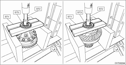
1. Remove the taper roller bearing using the ST.
| ST1 498077000 | REMOVER |
| ST2 899864100 | REMOVER |
| ST3 398497701 | SEAT |
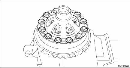
2. Remove the hypoid driven gear mounting bolt using the ST.
| ST 18270KA020 | SOCKET (E20) |
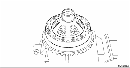
3. Remove the differential case (LH).
4. Remove the differential bevel gear and washer from differential case.
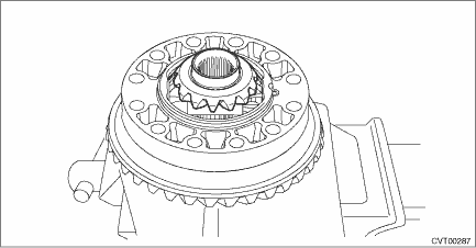
5. Remove the straight pin.
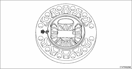
6. Remove the pinion shaft, then remove the differential bevel gear, washer and differential bevel pinion.
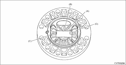
(A) | Pinion shaft |
(B) | Differential bevel gear |
(C) | Differential bevel pinion |
2. SIDE RETAINER
NOTE:
After adjusting the drive pinion backlash and tooth contact, replace the oil seal and O-ring with new parts.
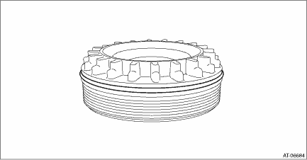
1. Remove the O-ring.
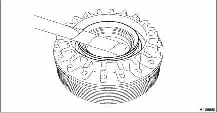
2. Remove the oil seal.
 Assembly
CONTINUOUSLY VARIABLE TRANSMISSION(TR580) > Front Differential AssemblyASSEMBLY1. DIFFERENTIAL CASE ASSEMBLY1. Install the washer and differential bevel gear into the differential case (RH).2. Inst ...
 Inspection
CONTINUOUSLY VARIABLE TRANSMISSION(TR580) > Front Differential AssemblyINSPECTION• Check each component for scratches, damage or other faults.• Using the ST, check the backlash of pinio ...
Other materials:
Removal
LIGHTING SYSTEM > Side Turn Signal Light AssemblyREMOVAL1. Disconnect the ground cable from battery. NOTE">2. Remove the light assembly - side turn mirror. Outer Mirror Assembly > DISASSEMBLY"> ...
Inspection
WIPER AND WASHER SYSTEMS > Combination Switch (Wiper)INSPECTION1. INSPECTION OF SWITCH UNIT1. Operate the switches to check the continuity between terminals. Switch positionTerminal No.StandardFrontOFFA1 and A3Less than 1 ?INTA1 and A3Less than 1 ?LOA2 and A3Less than 1 ?HIA2 and A4Less than 1 ?W ...
Dtc b1016 shift lock circuit
BODY CONTROL SYSTEM (DIAGNOSTICS) > Diagnostic Procedure with Diagnostic Trouble Code (DTC)DTC B1016 SHIFT LOCK CIRCUITDTC detecting condition:Open or power supply-output short, GND-output short in shift lock circuit.Trouble symptom:Shift lock does not be released or remain locked.Wiring diagram: ...
