
Subaru Crosstrek Service Manual: Disassembly
BRAKE > Front Disc Brake Assembly
DISASSEMBLY
CAUTION:
Be careful not to allow foreign matter to enter the brake hose connector.
1. Remove mud and foreign matter from the caliper body.
2. Remove the piston - disc brake.
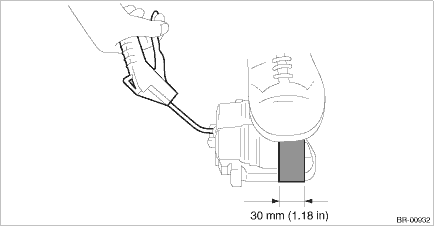
(1) Place a wooden block in the caliper body as shown in the figure to prevent the piston - disc brake from jumping out and being damaged.
(2) Using an air gun, gradually apply compressed air via the brake hose installation hole to push out the piston - disc brake.
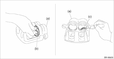
3. Remove the piston boot (b) and piston seal (c) from the caliper body cylinder (a).
CAUTION:
Do not damage the cylinder and piston seal groove.
4. Remove the guide pin - front brake, lock pin - front brake, lock pin - sleeve, and pin boot from the support - front disc brake.
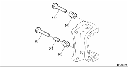
(a) | Guide pin - front brake (black) | (c) | Lock pin - sleeve | (d) | Pin boot |
(b) | Lock pin - front brake (silver) |
 Removal
BRAKE > Front Disc Brake AssemblyREMOVALCAUTION:Do not allow brake fluid to come in contact with the painted surface of the vehicle body. If it does, wash off with water and wipe away completely.1. ...
 Inspection
BRAKE > Front Disc Brake AssemblyINSPECTION1. Check the caliper body cylinder and piston for uneven wear, damage or rust.2. Check the rubber parts for damage or deterioration.3. If faulty is found ...
Other materials:
Diagnostics with phenomenon Inspection
AUTO HEADLIGHT BEAM LEVELER SYSTEM (DIAGNOSTICS) > Diagnostics with PhenomenonINSPECTION1. BEAM LEVEL CONTROL DOES NOT FUNCTIONCAUTION:• Before performing diagnosis, check the fuse in this circuit.• Initialization is required after replacing the auto headlight beam leveler CM.Wiring d ...
Removal
EXHAUST(H4DO) > MufflerREMOVALCAUTION:Vehicle components are extremely hot after driving. Be wary of receiving burns from heated parts.1. Turn the ignition switch to OFF.2. Lift up the vehicle.3. Remove the bolts and self-locking nuts which secure the rear exhaust pipe to the muffler.4. Apply a c ...
SRS airbag (Supplemental Restraint System airbag)
The Subaru Ascent is equipped with an advanced Supplemental Restraint System
(SRS), designed to work in combination with seatbelts to provide enhanced occupant
protection. The term “supplemental” indicates that airbags are intended to assist,
not replace, the primary restraint provided by ...
