Subaru Crosstrek Service Manual: Component
EMISSION CONTROL (AUX. EMISSION CONTROL DEVICES)(H4DO) > General Description
COMPONENT
1. CANISTER, LEAK CHECK VALVE ASSEMBLY AND DRAIN SEPARATOR
For structures of the canister, leak check valve assembly and drain separator, refer to “FU (H4DO)”. General Description > COMPONENT">
2. EGR SYSTEM 1
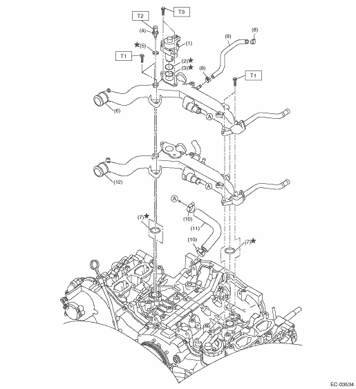
(1) | EGR control valve | (7) | O-ring | Tightening torque: N·m (kgf-m, ft-lb) | |
(2) | O-ring | (8) | Clip | T1: | 6.4 (0.7, 4.7) |
(3) | Gasket | (9) | Preheater hose A | T2: | 18 (1.8, 13.3) |
(4) | Engine coolant temperature sensor | (10) | Clip | T3: | 22 (2.2, 16.2) |
(5) | Gasket | (11) | Preheater hose B | ||
(6) | Water pipe ASSY (MT model) | (12) | Water pipe ASSY (CVT model) | ||
3. EGR SYSTEM 2
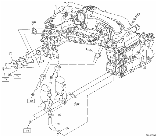
(1) | Gasket | (6) | Gasket | Tightening torque: N·m (kgf-m, ft-lb) | |
(2) | Gasket | (7) | Gasket | T1: | EGR Pipe > INSTALLATION"> |
(3) | EGR pipe | (8) | Clip | T2: | EGR Cooler > INSTALLATION"> |
(4) | EGR cooler (CVT model) | (9) | Engine coolant hose | ||
(5) | EGR cooler (MT model) | ||||
4. PCV SYSTEM 1
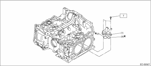
(1) | PCV connector | (3) | O-ring | Tightening torque: N·m (kgf-m, ft-lb) | |
(2) | O-ring | T: | 6.4 (0.7, 4.7) | ||
5. PCV SYSTEM 2
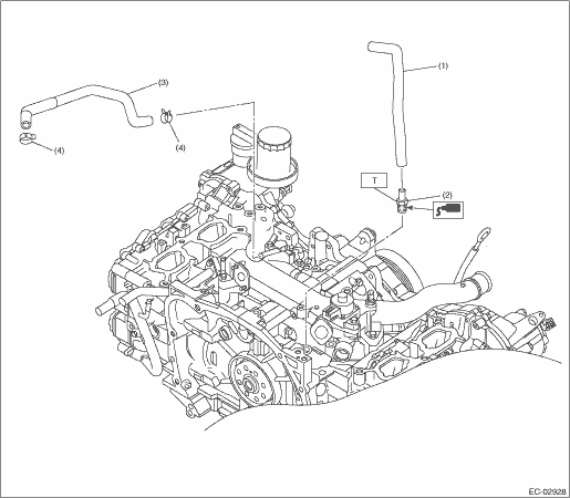
(1) | PCV hose A | (3) | PCV hose B | Tightening torque: N·m (kgf-m, ft-lb) | |
(2) | PCV valve | (4) | Clip | T: | 23 (2.3, 17.0) |
 Preparation tool
EMISSION CONTROL (AUX. EMISSION CONTROL DEVICES)(H4DO) > General DescriptionPREPARATION TOOL1. GENERAL TOOLTOOL NAMEREMARKSCircuit testerUsed for measuring resistance, voltage and current. ...

Other materials:
Connecting a smartphone
If you connect a smartphone to this
system after starting a supported aha
application on the smartphone, you can
display and operate the aha application
displayed on the smartphone on the
system screen.
1. Run the aha application on your
smartphone.
2. Connect the iPhone/iPod touch to th ...
Dtc b1620 side airbag sensor rh failure
AIRBAG SYSTEM (DIAGNOSTICS) > Diagnostic Chart with Trouble CodeDTC B1620 SIDE AIRBAG SENSOR RH FAILUREDIAGNOSIS START CONDITION:Ignition voltage is 10 V to 16 V.DTC DETECTING CONDITION:Side airbag sensor (RH) is faulty.When DTC B1620 is displayed, the circuit within the side airbag sensor (RH) i ...
Select play mode
The play mode settings display will appear
when play mode key is touched. Select
the preferred play mode from the following
items.
Icon
Function
Touch to start 1 track repeat.
Touch to start repeat all.
Touch to repeat the tracks in the
group.
...
