
Subaru Crosstrek Service Manual: Component
DRIVE SHAFT SYSTEM > General Description
COMPONENT
1. PROPELLER SHAFT
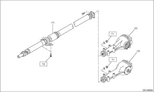
(1) | Propeller shaft | (3) | Rear differential (T-type) | Tightening torque: N·m (kgf-m, ft-lb) | |
(2) | Rear differential (VA1-type) | T1: | 31 (3.2, 22.9) | ||
T2: | 52 (5.3, 38.4) | ||||
2. FRONT AXLE
• EBJ + PTJ type
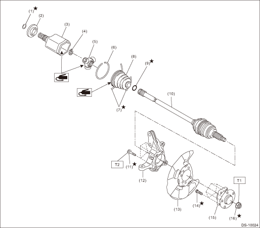
(1) | Circlip | (8) | Boot (PTJ) | (15) | Front hub unit bearing |
(2) | Baffle plate | (9) | O-ring | (16) | Axle nut |
(3) | Outer race (PTJ) | (10) | Shaft ASSY (EBJ) | ||
(4) | Snap ring | (11) | Bolt | Tightening torque: N·m (kgf-m, ft-lb) | |
(5) | Trunnion | (12) | Front axle housing | T1: | 220 (22.4, 162.3) |
(6) | Snap ring | (13) | Front brake back plate | T2: | 65 (6.6, 47.9) |
(7) | Boot band | (14) | Hub bolt | ||
3. REAR AXLE
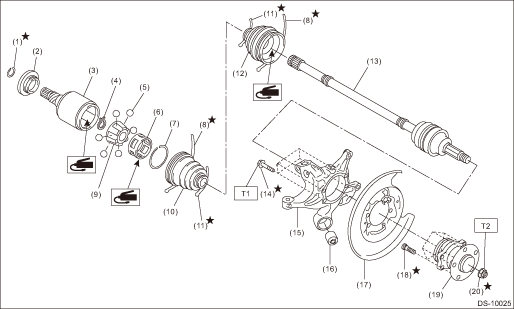
(1) | Circlip | (9) | Inner race | (17) | Rear brake back plate |
(2) | Baffle plate | (10) | Boot (DOJ) | (18) | Hub bolt |
(3) | Outer race (DOJ) | (11) | Boot band | (19) | Rear hub unit bearing |
(4) | Snap ring | (12) | Boot (BJ) Boot (EBJ) | (20) | Axle nut |
(5) | Ball | (13) | Shaft ASSY (BJ) (CVT model) Shaft ASSY (EBJ) (MT model) | ||
(6) | Cage | (14) | Bolt | Tightening torque: N·m (kgf-m, ft-lb) | |
(7) | Snap ring | (15) | Rear axle housing | T1: | 65 (6.6, 47.9) |
(8) | Boot band | (16) | Rear bushing | T2: | 190 (19.4, 140.1) |
 Specification
DRIVE SHAFT SYSTEM > General DescriptionSPECIFICATION1. PROPELLER SHAFTPropeller shaft typeEDJFront propeller shaft joint-to-joint length: L1CVT675.5 mm (26.59 in)MT735.5 mm (28.96 in)Rear propelle ...
 Preparation tool
DRIVE SHAFT SYSTEM > General DescriptionPREPARATION TOOL1. SPECIAL TOOLILLUSTRATIONPART NO.DESCRIPTIONREMARKS20099PA010INSTALLER & REMOVER• Used for replacing the rear bushing of rear axl ...
Other materials:
Dtc u0164 lost communication with hvac control module
INSTRUMENTATION/DRIVER INFO (DIAGNOSTICS) > Diagnostic Procedure with Diagnostic Trouble Code (DTC)DTC U0164 LOST COMMUNICATION WITH HVAC CONTROL MODULEDetected when CAN data is not received from A/C CM.NOTE:Perform the diagnosis for LAN system. Basic Diagnostic Procedure > PROCEDURE"> ...
Maximum load limits
WARNING
Never exceed the maximum load
limits explained in the following.
Exceeding the maximum load limits
could cause personal injury and/or
vehicle damage.
CAUTION
Adequate size trailer brakes are
required when the trailer and its
cargo exceed 1,000 lbs (453 kg)
total weight.
B ...
Removal
HVAC SYSTEM (HEATER, VENTILATOR AND A/C) > CondenserREMOVAL1. Using the refrigerant recovery system, discharge refrigerant. Refrigerant Recovery Procedure > PROCEDURE">2. Remove the air intake duct. Air Intake Duct > REMOVAL">3. Remove the clip, and remove the bracket - gr ...
