Subaru Crosstrek Service Manual: Blind spot detection/rear cross traffic alert
Note
Blind Spot Detection/Rear Cross Traffic Alert > Blind Spot Detection/Rear Cross Traffic Alert
NOTE
For procedure of each component in the Subaru Rear Vehicle Detection system, refer to the respective sections.
• Radar sensor: Radar Sensor">
• BSD/RCTA OFF switch: Switches and Harness">
• Combination meter: Combination Meter">
• Outer mirror assembly: Outer Mirror Assembly">
General description
Component
Blind Spot Detection/Rear Cross Traffic Alert > General Description
COMPONENT
1. RADAR SENSOR
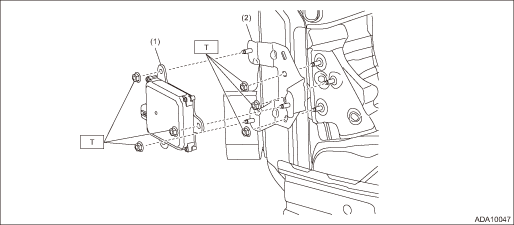
(1) | Radar sensor (master & slave) | (2) | Radar bracket | Tightening torque: N·m (kgf-m, ft-lb) | |
T: | 7.5 (0.8, 5.5) | ||||
Location
Blind Spot Detection/Rear Cross Traffic Alert > General Description
LOCATION
Refer to “LOCATION” of “Blind Spot Detection/Rear Cross Traffic Alert (DIAGNOSTICS)” section. Electrical Component Location > LOCATION">
Radar sensor
Installation
Blind Spot Detection/Rear Cross Traffic Alert > Radar Sensor
INSTALLATION
1. Install each part in the reverse order of removal.
Tightening torque:
Radar sensor and radar bracket: 7.5 N·m (0.8 kgf-m, 5.5 ft-lb)
2. Perform the adjustment of the radar sensor radar axis. Radar Sensor > ADJUSTMENT">
Switches and harness
Installation
Blind Spot Detection/Rear Cross Traffic Alert > Switches and Harness
INSTALLATION
BSD/RCTA OFF switch
Install each part in the reverse order of removal.
 Switches and harness
Inspection
Blind Spot Detection/Rear Cross Traffic Alert > Switches and HarnessINSPECTIONBSD/RCTA OFF switch1. Measure the resistance between connector terminals.Preparation tool:Circuit testerTer ...
 Combination meter Note
Blind Spot Detection/Rear Cross Traffic Alert > Combination MeterNOTEFor the operation procedures for combination meter, refer to “INSTRUMENTATION/DRIVER INFO” section. Combination Met ...
Other materials:
Component
EMISSION CONTROL (AUX. EMISSION CONTROL DEVICES)(H4DO) > General DescriptionCOMPONENT1. CANISTER, LEAK CHECK VALVE ASSEMBLY AND DRAIN SEPARATORFor structures of the canister, leak check valve assembly and drain separator, refer to “FU (H4DO)”. General Description > COMPONENT" ...
Inspection
PARKING BRAKE > Parking Brake Assembly (Rear Disc Brake)INSPECTION1. Measure the inner diameter of the rear disc rotor. If scoring or worn is found on the disc, replace the rear disc rotor.Disc rotor inner diameter:Specification: 170 mm (6.69 in)Service limit: 171 mm (6.73 in)2. Measure the linin ...
Inspection
COOLING(H4DO) > ThermostatINSPECTION1. Check that the thermostat does not have deformation, cracks or damage.2. Check that the thermostat valve closes completely at an ambient temperature.3. Immerse the thermostat and a thermometer in water. Raise water temperature gradually, and check the temper ...
