Subaru Crosstrek Service Manual: Assembly
EMISSION CONTROL (AUX. EMISSION CONTROL DEVICES)(H4DO) > Drain Separator
ASSEMBLY
Assemble in the reverse order of disassembly.
NOTE:
Connect the quick connector as shown in the figure.
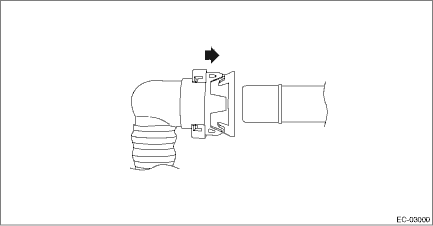
 Drain separator
...
 Removal
EMISSION CONTROL (AUX. EMISSION CONTROL DEVICES)(H4DO) > Drain SeparatorREMOVALThe drain separator is installed to the leak check valve assembly. Refer to “Leak Check Valve Assembly” fo ...
Other materials:
Operation
EyeSight (DIAGNOSTICS) > EyeSight Temporary Code(s) DisplayOPERATIONIf the EyeSight pause code is detected from the stereo camera, all the functions of the EyeSight excluding the conventional cruise control stop temporarily and cannot be used. When the failure is resolved, the function starts ope ...
Installation
SEAT BELT SYSTEM > Front Seat BeltINSTALLATION1. SEAT BELT OUTER - FRONTCAUTION:• The parts of the driver and passenger sides are not the same. Before installation, make sure that the correct part is used.• During installation, make sure that the seat belts are not twisted.• Aft ...
Dtc c2021 tire 1 air pressure low (normal mode)
TIRE PRESSURE MONITORING SYSTEM (DIAGNOSTICS) > Diagnostic Procedure with Diagnostic Trouble Code (DTC)DTC C2021 TIRE 1 AIR PRESSURE LOW (NORMAL MODE)NOTE:Refer to DTC C2024 for diagnostic procedure. Diagnostic Procedure with Diagnostic Trouble Code (DTC) > DTC C2024 TIRE 4 AIR PRESSURE LOW ( ...
