Subaru Crosstrek Service Manual: Assembly
DRIVE SHAFT SYSTEM > Rear Drive Shaft
ASSEMBLY
CAUTION:
Wrap shaft splines with vinyl tape to protect the boot from scratches.
NOTE:
Use specified grease.
Grease:
BJ, EBJ side: NKG814
DOJ side: NKG814
1. Install the inner race to the shaft.
(1) Install the boot (BJ) or boot (EBJ) in the specified position, and fill it with 50 to 60 g (1.76 to 2.12 oz) of specified grease.
(2) Place the boot (DOJ) at the center of shaft.
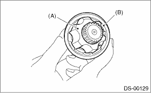
(3) Insert the cage onto shaft.
NOTE:
Insert the cage with the cutout portion facing the shaft end, since the cage has an orientation.

(A) | Cage |
(B) | Cutout portion |
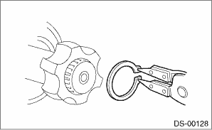
(4) Install the inner race on shaft and fix the snap ring in place with pliers.
NOTE:
Confirm that the snap ring is completely fitted in the shaft groove.
2. Install the cage to the inner race.
(1) Install the cage (B) with the protruding section aligned with the track on the inner race (A), and turn by a half pitch.
(2) Fill 80 to 90 g (2.82 to 3.17 oz) of the specified grease into the inner side of the outer race (DOJ).
(3) Apply a thin coat of specified grease to the cage pocket and ball.
(4) Insert the ball bearings into the cage pocket.
3. Connect the shaft assembly to the outer race (DOJ).
(1) Align the outer race (DOJ) track and ball positions, and place the shaft, inner race, cage and ball bearings in the original positions, and then fix outer race (DOJ) in place.
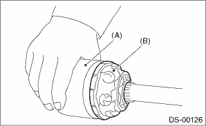
(A) | Outer race (DOJ) |
(B) | Grease |
(2) Install the snap ring in the groove of the outer race (DOJ).
CAUTION:
Be careful of the following items during installation:
• Make sure that the balls, cage and inner race are completely fitted in the outer race (DOJ).
• Use care not to place the matched position of snap ring in the ball groove of outer race (DOJ).
• Pull the shaft lightly and assure that the circlip is completely fitted in the groove.
(3) Apply an even coat of the specified grease [20 to 30 g (0.71 to 1.06 oz)] to the entire inner surface of boot (DOJ). Also apply grease to the shaft.
(4) Attach the boot (DOJ) taking care not to twist it.
NOTE:
• The inside of the large end of boot (DOJ) and the boot groove shall be cleaned so as to be free from grease and other substances.
• When installing the boot (DOJ), position the outer race (DOJ) at center of the stroke.
(5) Put a new boot band through the clip and wind twice in the band groove of the boot (DOJ).
(6) Pinch the end of boot band with pliers. Hold the clip and tighten securely.
NOTE:
When tightening boot, use care so that the air within the boot is appropriate.
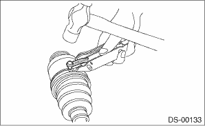
(7) Tighten the boot band using the ST.
NOTE:
Tighten the boot band until it cannot be moved by hand.
Preparation tool:
ST: BAND TIGHTENING TOOL (925091000)
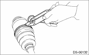
(8) Tap the clip with the punch provided at the end of the ST.
NOTE:
Tap to an extent that the boot underneath is not damaged.
Preparation tool:
ST: BAND TIGHTENING TOOL (925091000)
(9) Cut off the boot band with an allowance of about 10 mm (0.39 in) left from the clip and bend this allowance over the clip.
CAUTION:
Make sure that the end of the boot band is in close contact with clip.
4. Install the boot band to the boot (BJ) or boot (EBJ) in the same procedure as the boot (DOJ).
5. Extend and retract the DOJ repeatedly to provide an equal coating of grease.
 Rear drive shaft
...
 Removal
DRIVE SHAFT SYSTEM > Rear Drive ShaftREMOVAL1. Disconnect the ground cable from battery. NOTE">2. Lift up the vehicle, and then remove the rear wheels.3. Remove the axle nut.CAUTION:Do not ...
Other materials:
Dtc b161a lost communication with front satellite sensor bus
AIRBAG SYSTEM (DIAGNOSTICS) > Diagnostic Chart with Trouble CodeDTC B161A LOST COMMUNICATION WITH FRONT SATELLITE SENSOR BUSDiagnosis start condition:Ignition voltage is 10 V to 16 V.DTC detecting condition:• Harness between airbag control module and front sub sensor is open or shorted.&bul ...
Inspection
BRAKE > Brake BoosterINSPECTION1. OPERATION CHECK WHEN NOT USING MEASURING DEVICESCAUTION:When checking operation, be sure to apply the parking brake securely.When an operation check is performed with no measuring devices, a faulty part cannot be identified correctly. But it is possible to identi ...
General diagnostic table Inspection
WHEEL AND TIRE SYSTEM > General Diagnostic TableINSPECTIONSymptomsPossible causeCorrective actionWheel is out of balance.Improperly inflated tire.Adjust the tire pressure.Uneven wearCheck the tire referring to “Abnormal tire wear” in this table, carry out the procedure and replace the ...
