
Subaru Crosstrek Service Manual: Assembly
DRIVE SHAFT SYSTEM > Front Hub Unit Bearing
ASSEMBLY
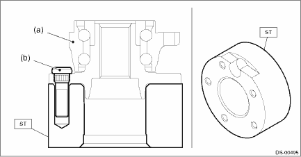
1. Install the hub unit bearing to the ST securely.
Preparation tool:
ST: HUB STAND (927080000)
2. Using a press, press the new hub bolts (b) until their seating surfaces contact the hub unit bearing (a).
NOTE:
Use the 12 mm (0.47 in) dia. holes in the HUB STAND to prevent bolts from tilting.

 Removal
DRIVE SHAFT SYSTEM > Front Hub Unit BearingREMOVAL1. Lift up the vehicle, and then remove the front wheels.2. Remove the axle nut.CAUTION:Do not loosen the axle nut while the front axle is loaded. ...
Other materials:
Electrical component location Location
CRUISE CONTROL SYSTEM (DIAGNOSTICS) > Electrical Component LocationLOCATION(1)Engine control module (ECM)(4)Cruise indicator light and cruise set indicator light(7)Neutral position switch (MT model)(2)Cruise control command switch(5)Transmission control module (TCM) (CVT model)(8)Clutch switch (M ...
Electrical specification
CONTROL SYSTEMS > AT Shift Lock Control SystemELECTRICAL SPECIFICATION• Model without push button ignition switchItemConnector No.Terminal No.Input/Output signalMeasured value and measuring conditionsBattery power supplyB28169 — 16 V7i846Ignition power supplyB2803210 — 15 V when ignitio ...
Shift lock function
The shift lock function helps prevent the
improper operation of the select lever.
The select lever cannot be operated
unless the ignition switch is turned to the
"ON" position and the brake pedal is
depressed.
The select lever cannot be moved from
the "P" position to any other positio ...
